ADAU1979
PRODUCTIONQuad Analog-to-Digital Converter (ADC)
- Part Models
- 2
- 1ku List Price
- Starting From $3.71
Part Details
- Four 4.5 V rms (typical) differential inputs
- On-chip phase-locked loop (PLL) for master clock
- Low electromagnetic interference (EMI) design
- 109 dB (typical) analog-to-digital converter (ADC) dynamic range
- Total harmonic distortion + noise (THD + N): −95 dB (typical)
- Selectable digital high-pass filter
- 24-bit stereo ADC with 8 kHz to 192 kHz sample rates
- Digital volume control with autoramp function
- I2C/SPI controllable for flexibility
- Software-controllable clickless mute
- Software power-down
- Right justified, left justified, I2S, and TDM modes
- Master and slave operation modes
- 40-lead LFCSP
- Qualified for automotive applications
The ADAU1979 incorporates four high performance, analog-to-digital converters (ADCs) with 4.5 V rms capable ac-coupled inputs. The ADCs use a multibit sigma-delta (Σ-Δ) architecture with continuous time front end for low EMI. An I2C/serial peripheral interface (SPI) control port is included that allows a microcontroller to adjust volume and many other parameters. The ADAU1979 uses only a single 3.3 V supply. The device internally generates the required digital DVDD supply. The low power architecture reduces the power consumption. The on-chip PLL can derive the master clock from an external clock input or frame clock (sample rate clock). When fed with the frame clock, it eliminates the need for a separate high frequency master clock in the system. The ADAU1979 is available in a 40-lead LFCSP package.
Note that throughout the data sheet, multifunction pins, such as SCL/CCLK, are referred to either by the entire pin name or by a single function of the pin, for example, CCLK, when only that function is relevant.
Applications
- Automotive audio systems
- Active noise cancellation systems
Documentation
Data Sheet 1
User Guide 1
Device Drivers 1
ADI has always placed the highest emphasis on delivering products that meet the maximum levels of quality and reliability. We achieve this by incorporating quality and reliability checks in every scope of product and process design, and in the manufacturing process as well. "Zero defects" for shipped products is always our goal. View our quality and reliability program and certifications for more information.
| Part Model | Pin/Package Drawing | Documentation | CAD Symbols, Footprints, and 3D Models |
|---|---|---|---|
| ADAU1979WBCPZ | 40-Lead LFCSP (6mm x 6mm w/ EP) | ||
| ADAU1979WBCPZ-RL | 40-Lead LFCSP (6mm x 6mm w/ EP) |
This is the most up-to-date revision of the Data Sheet.
Software Resources
Device Drivers 1
Evaluation Software 0
Can't find the software or driver you need?
Evaluation Kits
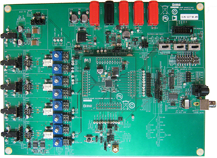
ADAU1977 Evaluation Board
Resources
Software
ADUSB2EBZ Evaluation Board
Features and Benefits
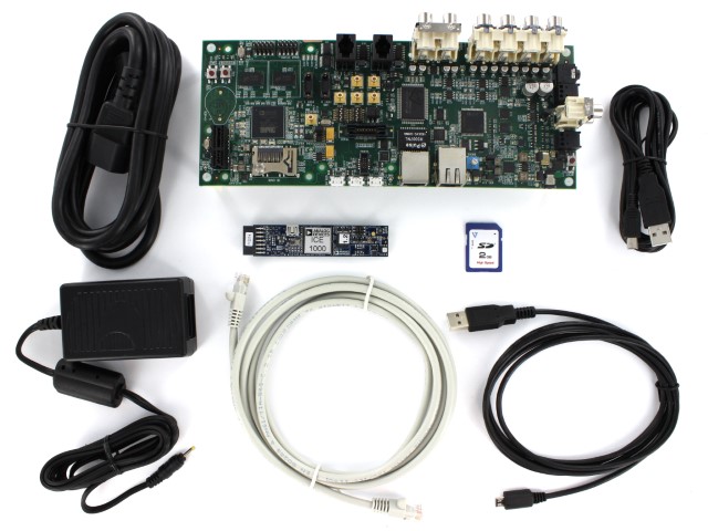
EVAL-ADUSB2EBZ "USBi"
|
Product Details
The Analog Devices USBi “USB Interface” (EVAL-ADUSB2EBZ) board is the interface between your PC's USB port and SigmaDSP hardware's data input pins. This interface can be used with any evaluation board which includes an External SPI/I²C header (Aardvark Header). The EVAL-ADUSB2EBZ board is capable of both SPI and I²C communication (which is user selectable) and can supply IOVDD of either 3.3V or 1.8V.The USBi interface is powered from the computer's USB port.
To Install the USBi Board:
- Connect the USB cable to the USBi Board a spare USB port on your PC.
- The Windows “Found New Hardware Wizard” will launch.
- Choose “Install from a list or a specific location” and click “Next”.
- Select “Search for the best driver in these locations” and Check the box for “Include this location in the search.”
- Press the “Browse” button and locate the appropriate driver file in the SigmaStudio application folder (default folder is C:\Program Files\Analog Devices Inc\Sigma Studio\USB drivers): Select the CyUSB.inf file.
- Click “Continue Anyway” if you're prompted with “This software has not passed Windows Logo testing.”
Using USBi in SigmaStudio:
To communication between SigmaStudio and the USBi board, a communication channel block must be added to the Schematic design. To locate the block, select the Hardware Configuration Tab, in the ToolBox or Tree ToolBox window choose the “Communication Channels” category, and select the USBi block.
This block provides connections for multiple processors (ICs / DSPs), allowing you to use multiple processors in a single design. This block allows you to explicitly specify both the communication protocol (SPI or I²C) and the part's address, I²C address or SPI catch line. The DSP hardware's address must match the block's selected address for communication to function properly. See the parts data sheet for more information about addressing (e.g. ADR_SEL, ADDR0, or ADDR1 pins). The default USBi protocol is I²C, to enable SPI, you must first select an SPI address in the block's drop down menu and then perform three write operations (e.g. press the write button the Register Read/Write Window 3 times). The USBi hardware has LEDs which indicate the current mode, I²C or SPI.
ADSP-SC589 Evaluation Hardware for the ADSP-SC58x/ADSP-2158x SHARC Family (529-ball CSPBGA)
Resources
ADSP-SC584 Evaluation Hardware for the ADSP-SC58x/ADSP-2158x SHARC Family (349-ball CSPBGA)
Resources
Latest Discussions
No discussions on ADAU1979 yet. Have something to say?
Start a Discussion on EngineerZone®