ADUCM430
RECOMMENDED FOR NEW DESIGNSPrecision Analog Microcontroller, 12-Bit Analog Input and Output with PMIC and TECC, Arm Cortex-M3
- Part Models
- 3
- 1ku List Price
- price unavailable
Part Details
- Analog input and output
- Multichannel, 12-bit, 2 MSPS ADC
- Up to 16 external channels
- Power, VDAC, IDAC, and temperature monitor internal channels
- Single-ended and differential modes
- 0 V to VREF analog input range
- Input buffer included
- Digital comparators
- Multichannel, 12-bit, 2 MSPS ADC
- Up to nine, 12-bit voltage output VDACs
- 4-channel, selectable output range
- 0 V to 2.5 V or AVDDx − 0.1 (4-channel on the ADuCM430/ADuCM431/ADuCM432 and 3-channel on the ADuCM433)
- AVDDNEG + 0.2 V to 0 V or −2.5 V to 0 V (4-channel on the ADuCM430 and 1-channel on the ADuCM433)
- 4-channel, selectable output range
- 4-channel, 0 V to 2.5 V or AVDDx − 0.2 V
- 1-channel, 0 V to 2.5 V
- 4-channel, configurable output range: 50 mA, 100 mA, or 150 mA (ADuCM430)
- 1-channel, configurable output range: 50 mA, 100 mA, or 150 mA (ADuCM433)
- Optional Buck or LDO regulator modes if not using TEC
- Maximum heating and cooling current: 1.3 A
- Current and voltage monitoring and protection
- Soft start function
- 32-bit Arm Cortex-M3 core, RISC architecture
- Serial wire port supports code download and debug
- 16 MHz on-chip oscillator
- 80 MHz PLL output
- External clock source
- Memory
- Up to 2× 512 kB independent Flash/EE memories
- 48 kB SRAM
- Software triggered, in circuit reprogrammability via I2C
- On-chip peripherals
- 1× UART, 2× SPI, 2× I2C serial input and output
- GPIO with multilevel voltage (3.3 V, 1.8 V, and 1.2 V) digital inputs
- MDIO target up to 4 MHz (open drain)
- 3× 16-bit and 1× 32-bit general-purpose timers
- Wake-up timer (WUT)
- Watchdog timers (WDT)
- 32 element PLA
- 16-bit PWM
- Manchester encoder and decoder
- All GPIOs support external interrupt
- Power
- Multiple supplies
- AVDDx, IOVDDx, DVDD, and PVDDTECx : 2.85 V to 3.63 V
- AVDDNEG (ADuCM430/ADuCM433): −1.8 V to −3.63 V
- PVDDIDACxx/PVDDIDAC (ADuCM430/ADuCM433): 1.60 V to AVDDx
- Multiple supplies
- Flexible operating modes for low power applications
- 5 mm x 5 mm, 0.4 mm pitch, 121-ball CSP_BGA
- 5 mm x 5 mm, 0.4 mm pitch, 72-ball CSP_BGA
- Fully specified for TJ = –40°C to +125°C
- Low cost QuickStart development system, which is available upon request from InfoOpticalNetwork@analog.com
- Full third-party support
Applications
- Optical networking—100G/200G/400G and higher frequency modules
For more information on the ADuCM430, contact InfoOpticalNetwork@analog.com.
Documentation
ADI has always placed the highest emphasis on delivering products that meet the maximum levels of quality and reliability. We achieve this by incorporating quality and reliability checks in every scope of product and process design, and in the manufacturing process as well. "Zero defects" for shipped products is always our goal. View our quality and reliability program and certifications for more information.
| Part Model | Pin/Package Drawing | Documentation | CAD Symbols, Footprints, and 3D Models |
|---|---|---|---|
| ADUCM430BBCZ | CHIP SCALE BGA | ||
| ADUCM430BBCZ-RL | CHIP SCALE BGA | ||
| ADUCM430BBCZ-RL7 | CHIP SCALE BGA |
| Part Models | Product Lifecycle | PCN |
|---|---|---|
|
Jun 27, 2022 - 22_0122 ADuCM430 change of die adhesive material |
||
| ADUCM430BBCZ | ||
| ADUCM430BBCZ-RL | ||
| ADUCM430BBCZ-RL7 | ||
This is the most up-to-date revision of the Data Sheet.
Software Resources
Can't find the software or driver you need?
Request a Driver/SoftwareEvaluation Kits
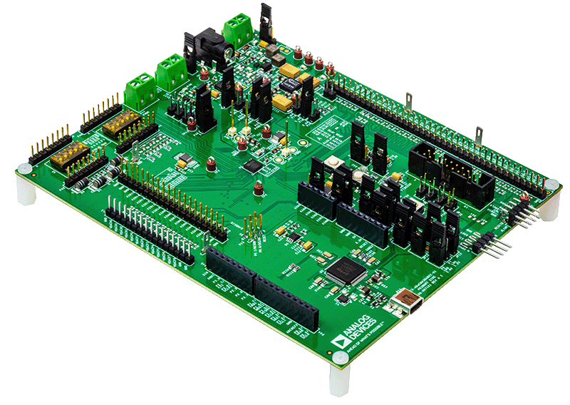
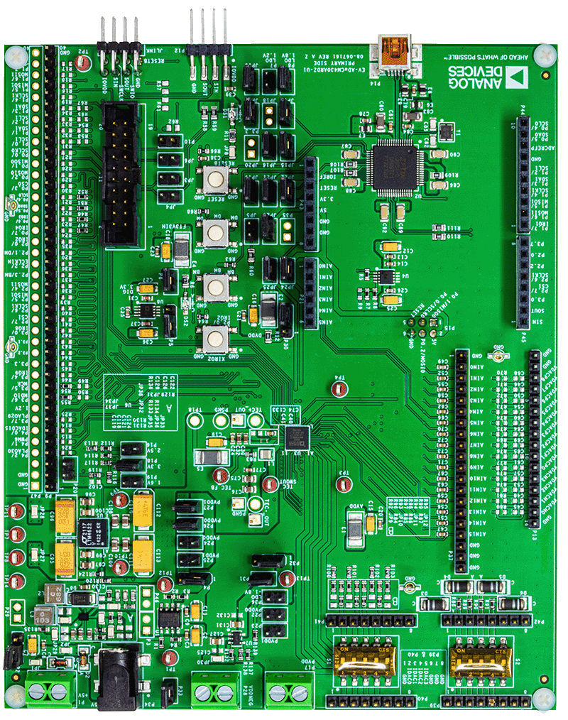
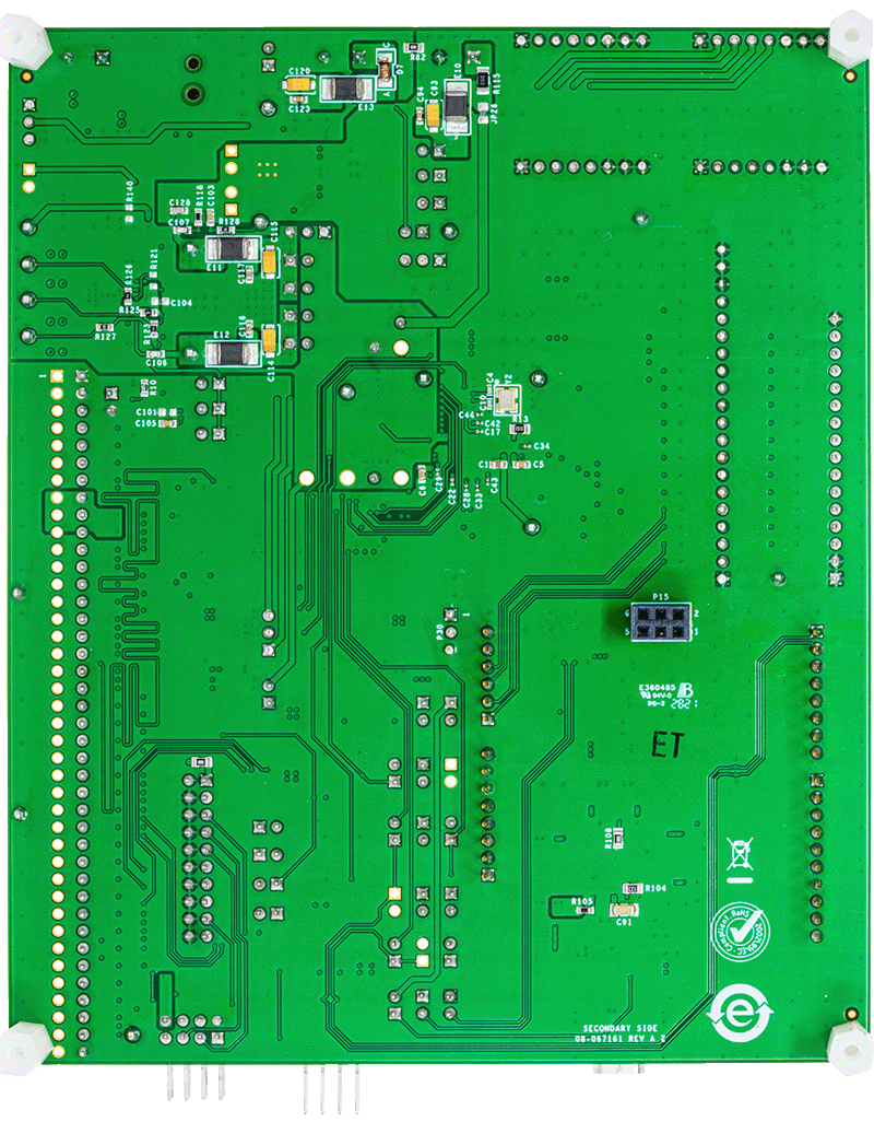
ADuCM430 Development System
Latest Discussions
No discussions on ADUCM430 yet. Have something to say?
Start a Discussion on EngineerZone®