Using the MAX15005 Supply and Driver for an LED Application
The reference design below provides a reference design for an automotive LED application. The MAX15005 is used to boost a standard, 8V to 16V car battery to 21V in order to drive a string of 6 to 8 LEDs. Key specifications for this reference design are listed below, along with a detailed schematic (Figure 1) and the bill of materials (Table 1) needed for this application.
Specifications
- VIN: 8V to 16V (Continuous), 40V (Transient)
- VLED+ Supply Voltage: 21V ±5% at 80mA (max)
- VLED+ Load Range: 10V to 20V at 70mA
- ILED: 70mA ±5%
- Dimming Input: 400Hz, 50Ω, Open Collector
- Dimming Resolution: 3µs
- Switching Frequency: 385kHz
- Operating Temperature: -40°C to +125°C
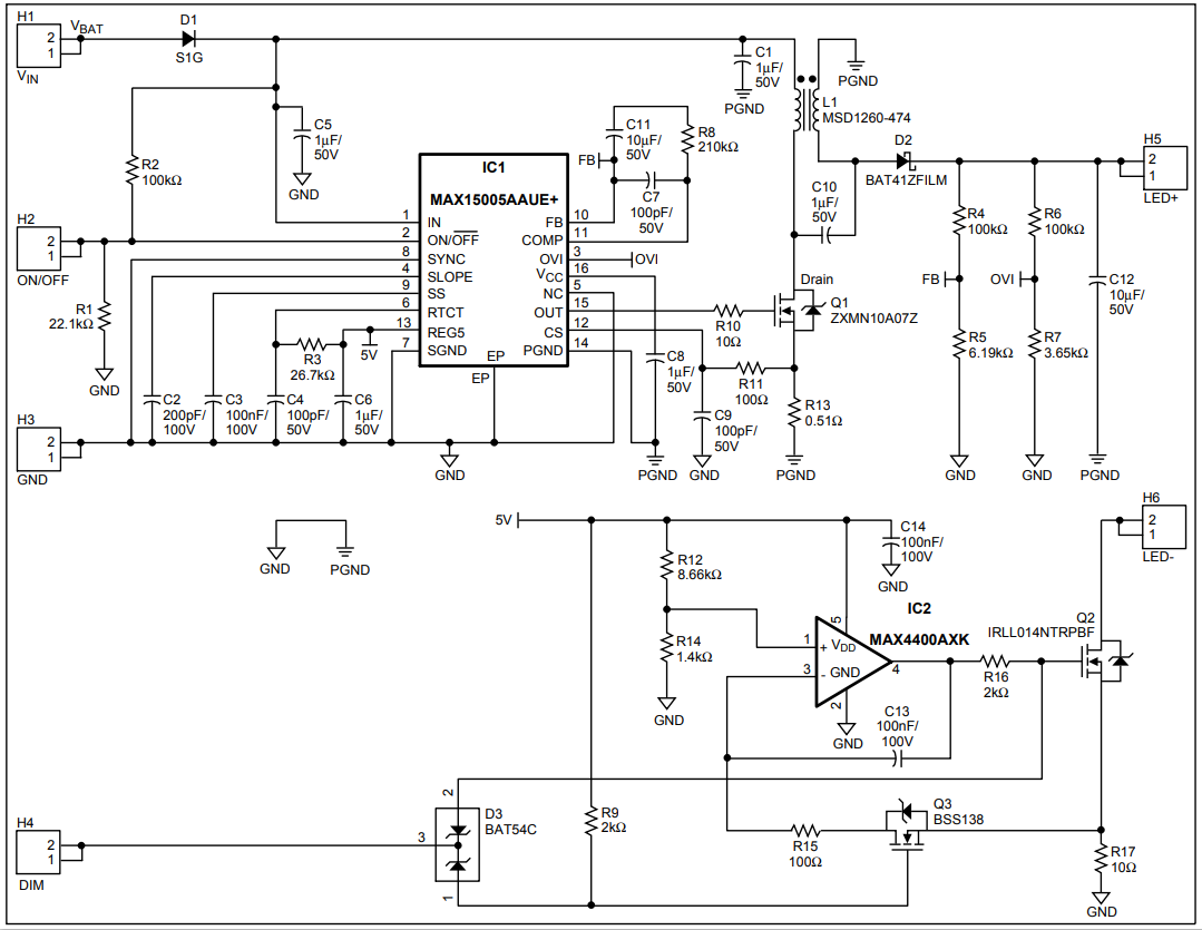
Figure 1. MAX15005 reference design
| Designator | Value | Description | Part | Footprint | Manufacturer | Quantity |
| C1, C5, C6, C8, C10 | 1µF/50V | Capacitors | GCM31MR71H105KA55L | 1206 | Murata | 5 |
| C2 | 200pF/100V | Capacitor | GRM2165C2A201JA01D | 0805 | Murata | 1 |
| C3, C13, C14 | 100pF/50V | Capacitors | GRM2165C1H101JA01D | 0805 | Murata | 3 |
| C4, C7, C9 | 100pF/50V | Capacitors | GRM2165C1H101JA01D | 0805 | Murata | 3 |
| C11 | 10nF/50V | Capacitor | GRM216R71H103KA01D | 0805 | Murata | 3 |
| C12 | 10µF/50V | Capacitor | UUD1H100MCL1GS | SMD | Nichocon | 1 |
| D1 | 1A/400V | Diode | S1G | SMA | Fairchild | 1 |
| D2 | 200mA/100V | Schottky Diode | BAD41ZFILM | SOD123 | STM | 1 |
| D3 | 200mA/30V | Schottky Diode | STM | SOT23 | STM | 1 |
| L1 | 470µF/0.86A | Inductor | MSD1260-474 | SMD | Coilcraft | 1 |
| Q1 | 1A/100V | n-FET | ZXMN10A07Z | SOT89 | Zetex | 1 |
| Q2 | 2A/55V | n-FET | IRLL014NTRPBF | SOT223 | International Rectifier | 1 |
| Q3 | 220mA/50V | n-FET | BSS138 | SOT23 | Fairchild | 1 |
| R1 | 22.1kΩ | Resistor | SMD, 1%, 0.125W | 0805 | Vishay | 1 |
| R2, R4, R6 | 100kΩ | Resistors | SMD, 1%, 0.125W | 0805 | Vishay | 3 |
| R5 | 6.19kΩ | Resistor | SMD, 1%, 0.125W | 0805 | Vishay | 1 |
| R7 | 3.65kΩ | Resistor | SMD, 1%, 0.125W | 0805 | Vishay | 1 |
| R8 | 210kΩ | Resistor | SMD, 1%, 0.125W | 0805 | Vishay | 1 |
| R3 | 26.7kΩ | Resistor | SMD, 1%, 0.125W | 0805 | Vishay | 1 |
| R9, R16 | 2kΩ | Resistors | SMD, 1%, 0.125W | 0805 | Vishay | 2 |
| R10 | 10Ω | Resistor | SMD, 1%, 0.125W | 0805 | Vishay | 1 |
| R11 | 100Ω | Resistor | SMD, 1%, 0.125W | 0805 | Vishay | 1 |
| R12 | 8.66kΩ | Resistor | SMD, 1%, 0.125W | 0805 | Vishay | 1 |
| R13 | .051kΩ | Resistor | SMD, 1%, 0.125W | 0805 | Vishay | 1 |
| R14 | 1.4kΩ | Resistor | SMD, 1%, 0.125W | 0805 | Vishay | 1 |
| R15 | 100Ω | Resistor | SMD, 1%, 0.125W | 0805 | Vishay | 1 |
| R17 | 10Ω | Resistor | SMD, 1%, 0.205W | 1206 | Vishay | 1 |
| IC1 | MAX15005A | Boost Controller | MAX15005AAUE+ | 16-TSSOP-EP | Maxim | 1 |
| IC2 | MAX4400 | Single Op-Amp | MAX4400AXK+ | 5-SC70 | Maxim | 1 |
The oscilloscope photos in Figures 2, 3, and 4 show the switching waveforms for this reference design at three different dimming conditions.
Figure 2. Waveform measurements for ILED at VIN = 14V with dimming at 50.0%
Figure 3. Waveform measurements for ILED at VIN = 14V with dimming at 0.1%
Figure 4. Waveform measurements for ILED at VIN = 14V with dimming at 99.9%
Related to this Article
{{modalTitle}}
{{modalDescription}}
{{dropdownTitle}}
- {{defaultSelectedText}} {{#each projectNames}}
- {{name}} {{/each}} {{#if newProjectText}}
-
 {{newProjectText}}
{{/if}}
{{newProjectText}}
{{/if}}
{{newProjectTitle}}
{{projectNameErrorText}}
Latest Media 21
