Design Note 160: Dual PowerPath Controller Simplifies Power Management
As the demand for portable electronics with multiple batteries continues to grow, so does the need for simple and efficient solutions for switching between batteries. The LTC1473 simplifies the design of circuitry for switching between two batteries or a battery and an AC adapter.
The LTC1473 is designed to drive two sets of low loss, back-to-back N-channel MOSFET switches to route power where needed, typically to the input of the main system switching regulator. An internal micropower boost regulator supplies the gate drive for the N-channel MOSFET switches.
The LTC1473 simplifies the designer’s task by incorporating a number of protection features. Short-circuit protection shuts off the gate drive when a fault condition exceeds the user-programmable time limit, inrush current limiting limits the current flowing into or out of the system bypass capacitor and a diode default mode allows power to flow from the highest potential until the inputs can be defined.
Automatic Switchover Between Battery and AC Adapter
A protected automatic switchover between a battery and a power source connected at DCIN can be constructed using the circuit in Figure 1. Under normal conditions, this circuit will route the voltage at DCIN to the output.
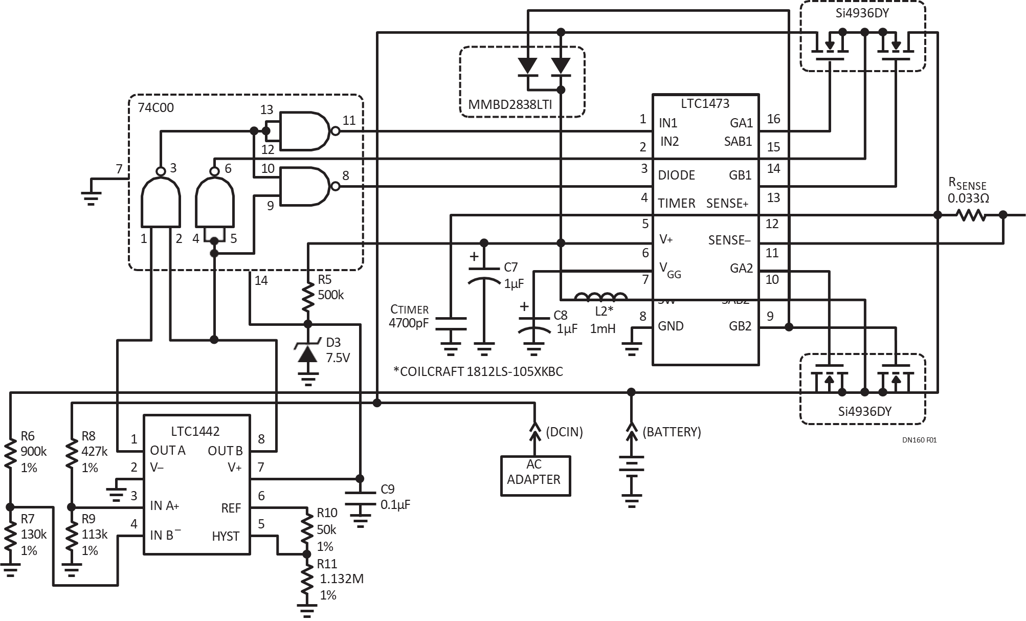
Figure 1. Protected Automatic Switchover Between Battery and AC Adapter.
If the voltage at DCIN drops below 9.75V, DCIN is deselected and the battery voltage is routed to the output. If the battery voltage is less than 5.9V, each switch is made to mimic a diode, allowing power to flow from the highest potential source to the output. In this “2-diode” mode, the first half of each PowerPath switch pair is turned on, and the second half is turned off. Thus, two diodes are formed by the body diodes of the MOSFET switches that are turned off.
The inrush current limit of 6A is selected with a 0.033Ω RSENSE resistor. The fault timer is set to 1.1ms with a 4700pF CTIMER capacitor. If a MOSFET switch is in current limit for more than 1.1ms, an internal latch in the LTC1473 is set and the MOSFET switch is turned off.
The LTC1442 shown in Figure 1 is an ultralow power dual comparator with a precision 1.182V reference. This comparator monitors the voltage at DCIN and the battery voltage and selects which MOSFET switch to turn on. Simple logic, comprising CMOS NAND gates, decodes the comparator outputs to control the inputs of the LTC1473. A 7.5V Zener shunt regulator in series with a 500k resistor supplies power for both the CMOS NAND gates and the LTC1442.
Power Routing Circuit for Microprocessor Controlled Dual Battery Systems
The microprocessor controlled dual battery system shown in Figure 2 uses two LTC1473s to provide input power routing and battery charging multiplexing. The two batteries can be of different chemistries. One LTC1473 is used to connect the output of the charger to the battery; the other connects the battery to the input of the system switching regulator.
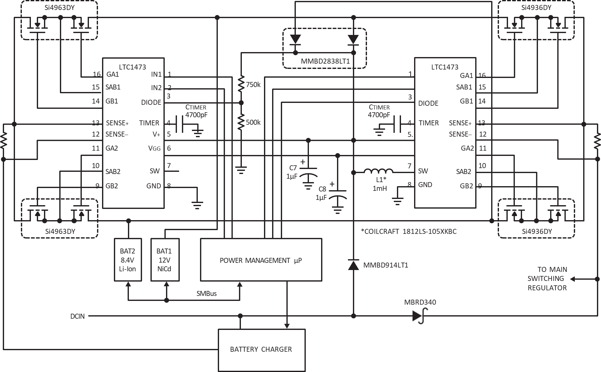
Figure 2. Power Routing Circuit for Microprocessor Controlled Dual Battery System.
The power-management microprocessor provides overall control of the power management system in concert with the two LTC1473s and the auxiliary power-management systems. The microprocessor decides which battery to connect to the input of the system switching regulator and which battery is in need of recharging. To charge a battery, the microprocessor selects the charging algorithm for that particular battery chemistry.
著者