

Overview
設計リソース
設計/統合ファイル
- MAXREFDES150MAIN
- Schematic
- BOM
- PCB Layout
- MAXREFDES150LED
- Schematic
- BOM
- PCB Layout
- MAXREFDES150ATACH
- Schematic
- BOM
- PCB Layout
デバイス・ドライバ
コンポーネントのデジタル・インターフェースとを介して通信するために使用されるCコードやFPGAコードなどのソフトウェアです。
説明
Industry 4.0, the fourth revolution in manufacturing and process automation, poses a considerable challenge for PLC design engineers who are required to pack more functionality into enclosures that keep getting smaller. Higher I/O (input/output) density and smaller form factors also add to the design challenge in another basic way, a consequence of the inevitable power dissipation. The system must be more power efficient than ever to keep the PLC from overheating, especially in an application where fans and vents are generally not acceptable. Fortunately, new solutions are being developed by companies, such as Maxim Integrated, who are looking to leverage their integration capabilities in the evolving industrial market.
Learn more: New Go-IO Industrial IoT Reference Design ›
機能と利点
- Two analog input channels ±12V, differential, 0V to +12V range per pin, 24-bit ADC
- Two analog input channels ±24mA, 24-bit ADC
- Analog output channel 0V to ±12V, 16-bit DAC
- Eight digital input channels 36V (max) configurable for IEC® 61131-2 input types 1, 2, and 3
- Eight digital output channels; 640mA high-side switches or 640mA push-pull at 24V
- Two RS-485 COM ports; half-duplex up to 42Mbps data rate
- Three DC-motor controllers: 9V to 32V full-bridge DC-motor drivers, up to 2.5A peak motor current (supplied by separate power supply)
- Four IO-Link master ports with M12 female connectors
- Fully IO-Link version 1.1 compliant
- TEConcept IO-Link master stack
Details Section
Introduction
Analog Device's new Pocket IO™ development platform is a reference design integrating a total of 30 IO's consisting of four analog inputs, one analog output, eight digital inputs, eight digital outputs, two RS485 (Profibus-capable field busses), three encoder motor-control ports, and four IO-Link® masters. Analog Device’s Pocket IO technology demonstration platform shows how analog integration can enable lower heat dissipation and faster throughput in a footprint that is less than ten cubic inches. Pocket IO connectivity is through USB or its own Wi-Fi® network. Code can be developed to run on the Intel® Edison using the popular and easy to use open-source Arduino®software IDE.
Detailed Description of Hardware
Pocket IO is the brand name for MAXREFDES150#. The MAXREFDES150# consists of three different boards. The overall system block diagram is shown in Figure 1.
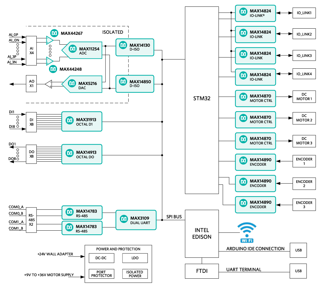
Figure 1. MAXREFDES150# system block diagram.
The ICs for the main functional blocks are within the Pocket IO case (the two boards are MAXREFDES150MAIN# and MAXREFDES150LED#) while the connectors are on a separate board (called MAXREFDES150ATACH#) which connects to Pocket IO using two 40-pin cable assemblies.
The control program for Pocket IO runs on the Intel Edison board, which is mounted on the MAXREFDES150MAIN# board. Separate STM microcontrollers are used to support the IO-Link masters (TEConcepts stack) and the DC-motor drivers.
Power Supplies
A single 24V, 1A supply is used to power the Pocket IO and internal DC-DC, and LDO circuits are used to generate the various different voltage levels required by the analog and digital devices. Note: The maximum load this adapter can supply is 1A, which limits how many of the digital outputs are switching loads simultaneously since each of the eight outputs can handle loads of up to 640mA each. The user can use a different 24V supply with 5A (max) capacity. The 24V, 1A supply connects to the block barrel connector, shown on the left in Figure 2.
Pocket IO has three DC-motor controllers, each of which can support +9V to +32V full-bridge DC-motor drivers at up to 2.5A peak motor current. In order to support these higher voltages and currents, a separate user-supplied power supply is required, and connects to Pocket IO through the green three-way terminal. Terminal 1 is used (with Terminal 3) to test the polarity of the external supply (to protect Pocket IO motor drivers from reverse polarity connections). In normal-use mode Terminal 2 is the +9V to +32V connection and Terminal 3 is the ground or 0V connection.
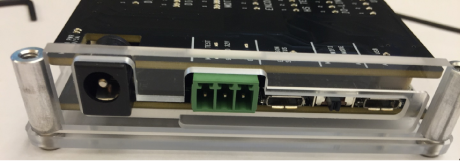
Figure 2. MAXREFDES150# power inputs.
Connections
The main functional blocks are on the two PCBs within the Pocket IO case while the connectors are on a separate board, called MAXREFDES150ATACH# shown in Figure 3.
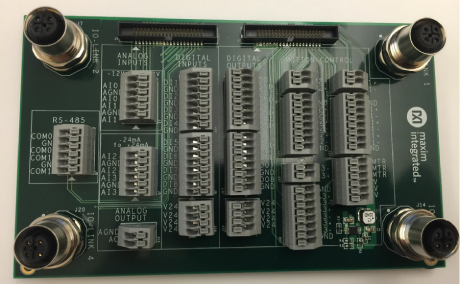
Figure 3. MAXREFDES150ATACH#
LED Indicators
Figure 4 explains the functions of the LED indicators for MAXREFDES150#.
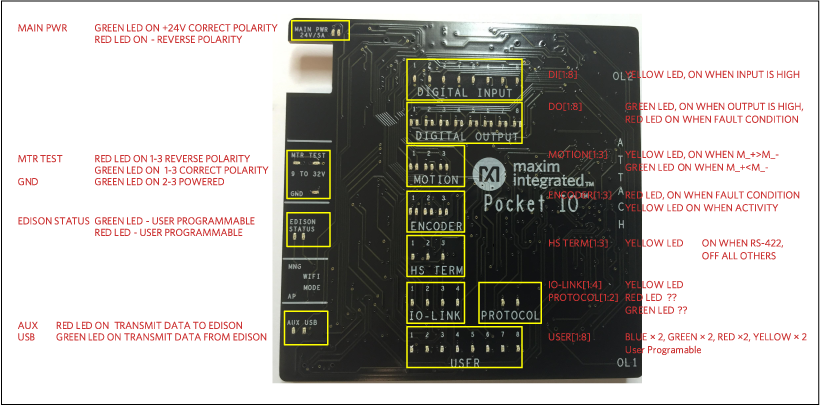
Figure 4. Pocket IO LEDs.
Hardware Sections
Analog IO
ADC Analog Inputs (pages 2-6 of MAXREFDES150MAIN# schematics)
The heart of the analog front end (AFE) is the MAX11254, a 6-channel, 24-bit delta-sigma ADC that achieves exceptional performance while consuming very low power. The MAX11254 communicates through an SPI serial interface to the Edison processor. Four channels are used; channels 0 and 1 are configured for voltage inputs and channels 2 and 3 for current inputs.
Voltage Reference
MAX6126 precision voltage reference is used to generate a 3.0V reference signal (VREFAO for DAC), which feeds a resistor divider to create 1.5V input to a MAX44244 precision low power op amp configured as a unity-gain buffer, providing a 1.5V reference signal (VREFAI for ADC).
Voltage Inputs
Two op amps are used to provide signal conditioning for each of the inputs to ADC channels 0 and 1. Each channel has a ‘positive’ and ‘negative’ input pair to provide a differential input range of 12V, 0V to +12V range per pin. The first amp uses MAX44267, which is a Beyond-the-Rails™ amplifier capable of providing a bipolar output from a single positive +15V supply. The second stage uses a MAX44248 configured as an inverting attenuator centered around 1.5V input level, providing an input to the ADC channel of ±1.38V differential. The input range for analog inputs 0 and 1 is 0V to +12V range per pin and it is recommended to use the voltage calibration sketch, which performs a 2-point calibration and stores gain and calibration values in the MAX11254 to provide over 0V to +10V range commonly found in industrial applications.
Note: The inputs can accept signals to +13V before the ADC input range of ±1.5V is exceeded, providing extra headroom beyond the recommended operating range.
Current Inputs
Two op amps, two FETs and a TVS are used to provide signal conditioning for the inputs to ADC channels 2 and 3. Overcurrent protection is provided by the two FETs, which ‘opens’ if the input current exceeds 50mA to 70mA. In addition, the TVS triggers if the input voltage is > 24V and the series resistor limits current to the op amp to avoid damaging the op amps. The input current (±24mA) is converted to a voltage by a 15.4Ω resistor producing ±370mV, which is buffered by a MAX44267 amplifier, and then attenuated by a MAX44248 amplifier with a gain of 0.95V to produce a differential input voltage to the ADC, channels 2 and 3, of ±352mV.
Power Supplies
The analog I/O section has isolated data and power that provide low noise 15V (AV15V) and 3.6V (AV3V6) rails with respect to analog ground (AGND). Refer to the section on the power tree for details about how these rails are generated.
DAC Analog Outputs (page 8 of MAXREFDES150MAIN# schematics)
MAX5216 is a 16-bit, low-power, buffered output, rail-to-rail DAC with an SPI Interface for interfacing to the Intel Edison. The 3.0V reference signal (VREFAO) generated from MAX6126 is used to set the full-scale range of the MAX5216. A precision, low-noise, wide-band amplifier, MAX9632 is used to provide a gain of 4, giving an output range for AO of 0V to +12V. To ensure the output can truly go to zero volts the negative supply of the MAX9632 is powered from a -3V supply (AVM3V).
Digital Isolation (page 9 of MAXREFDES150MAIN# schematics)
Two different digital isolators are used to provide data signal isolation for the analog I/O section. MAX14130 is a four-channel digital isolator used to isolate the SPI signals for CLK, MOSI and the two-chip select signals for the ADC and DAC. The MAX14130 also provides voltage translation between the 1.8V signals from the Edison and the 3.6V signals from the ADC and DAC. MAX14850 is a six-channel digital isolator with four unidirectional channels (2-2) and two bidirectional channels. The unidirectional channels are used to transfer CLR and RESET signals to the data converters and to return the RDY and SPI_MISO signals to the Edison.
Digital IO
Digital Inputs (page 12 of MAXREFDES150MAIN# schematics)
MAX31913 is an industrial, octal, digital-input translator-serializer. On-chip serialization takes the eight input channels, and outputs data through the SPI interface to the Intel Edison. The device features input-current limiting, allowing a significant reduction in consumed power, which is set by a single 15kΩ resistor (R806) connected to the RIREF pin, setting the current limit at 2.4mA. A series 2.2kΩ resistor on each input ensures the device is compatible with IEC 61131-2 Input Types 1, 2, and 3. The MAX31913 is powered from a single +5V supply removing the need for a 24V supply to this IC. Two software addressable bits, DI_DB0 and DI_DB1 control selectable on-chip low-pass filters allowing flexible debouncing and filtering of sensor outputs based on the application. 8 LEDs are used to show the status of each digital input channel.
Digital Outputs (page 13 of MAXREFDES150MAIN# schematics)
MAX14913 is a digital-output-octal high-speed, high-side switch/push-pull 24V driver capable of 200kHz switching rate, The MAX14913 has eight 640mA smart high-side switches that can also be configured as push-pull drivers for high-speed switching. The device is configured and controlled through the SPI interface. The 4 x 4 LED driver crossbar matrix is used for driving 16 LEDs to indicate per-channel output status and the fault conditions. Care needs to be taken when selecting the output loads to ensure they do not exceed the 1A capability of the power adapter supplied. For higher currents, a different supply is required.
Motor Control
DC Motor Driver (page 20 of MAXREFDES150MAIN# schematics)
MAX14870 motor drivers provide a small, low-power and simple solution for driving and controlling brushed DC motors and relays with voltages between 9V and 32V. Very low driver on-resistance reduces power dissipation. Input power for theses circuits is supplied by the green connector, which supports up to 2.5A motor current.
Motor Encoder (pages 14 and 15 of MAXREFDES150MAIN# schematics)
MAX14890 incremental encoder receiver contains four differential receivers and two single-ended receivers. The differential receivers can be operated in RS-422 or differential high-threshold logic (HTL) modes and are optionally configurable for single-ended TTL/HTL operation.
IO-Link (pages 3 to 5 of MAXREFDES150LED# schematics)
The MAX14824 is an IO-Link master interface that integrates an IO-Link physical layer transceiver with an auxiliary digital input and two linear regulators. High port count IO-Link master applications are supported through in-band SPI addressing, and the SPI interface minimizes host controller access times. In-band addressing and selectable SPI addresses enable cascading up to 16 devices although in this design only four devices are implemented. The device is IO-Link v.1.0 and v.1.1 physical layer compliant and supports all the IO-Link data rates (COM1, COM2, and COM3). The driver is guaranteed to drive up to 300mA (min) load currents and features slew-rate-controlled drivers to reduce EMI.
The 4-port IO-Link master uses TEConcept’s IO-Link master stack, with the software running on a STM32F103 ARM® Cortex® M3 microcontroller (U1101). The four MAX14824’s (U1201/U1301/U1401/U1501) each connect to a UART in the STMF103 as well as through a local SPI bus for configuration. MAXREFDES150# ships with the master stack preprogrammed inside the MAXREFDES150# hardware with an indefinite time license. For further information about TEConcept and their software, contact TEConcept GmbH:
TEConcept GmbH
Wentzingerstr. 21
D-79106 Freiburg
Tel. +49 761 21443640
Fax +49 761 21443631
Email: info@teconcept.de
www.teconcept.de/Contact.php
Communication Ports (page 10 of MAXREFDES150MAIN# schematics) RS-485 Interface
Two RS-485 interfaces (COM0 and COM1) are provided using the MAX14783E, a half-duplex RS-485/422 transceiver that operates at either 3.3V or 5V rails with high ±35kV ESD performance and up to 42Mbps data rate. For MAXREFDES150# the two devices (U1001 and U1003) operate from a 3.3V supply and connect their driver and receiver connections to individual ports of the MAX3109 dual UART. The RS-485 ‘cable’ pins (A and B) are connected directly to the RS-485 connector on MAXREFDES150ATACH# card.
UART
The two RS-485 transceivers connect to a MAX3109 advanced dual universal asynchronous receiver-transmitter (UART), which has 128 words of receive and transmit first-in/first-out (FIFO) and connects using a high-speed SPI interface to the Intel Edison.
Power Supplies
The power tree for MAXREFDES150# is shown in Figure 5.
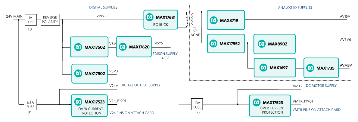
Figure 5. MAXREFDES150# power tree.
The two power inputs are the 24V MAIN using the barrel connector and the VMTR using the green connector. When used with the supplied 24V adapter, the maximum current available is 1A, which limits the user in terms of the digital-output loads, which can be switched. The ‘digital supplies’ and the ‘analog IO supplies’ are protected from reverse polarity and overcurrent using a 1A fuse (F3). The MAX17502 high-efficiency, high-voltage, synchronous step-down DC-DC converter with integrated MOSFETs operates over a 4.5V to 60V input voltage range. This device is offered in a fixed 3.3V, 5V, or adjustable output voltage (0.9V to 92%VIN) while delivering up to 1A of current. The output voltage is accurate to within ±1.7% over -40°C to +125°C. Two MAX17502s are used to generate the 5V (V5V) and 3.3V (V3V3) rails. Intel Edison requires a 4.3V supply, with a MAX17620, high-frequency, high-efficiency synchronous step-down DC-DC converter used to generate VSYS from the 5V input. MAX17620 operates over a 2.7V to 5.5V input-voltage range and supports VOUT up to 100%. High-frequency operation enables the use of small, low-cost inductors and capacitors making it ideal for small form-factor solutions such as Pocket IO.
If the user wishes to run higher current loads for the digital outputs, a higher capacity supply (V24V) needs to be connected to the barrel connector. The circuit is designed to support up to 5A loads and is protected from over current by F1 a 6.3A fuse. The 24V supply (V24) is brought out to MAXREFDES150ATACH# to provide the user a flexible 24V source. These pins are protected from accidental short circuits using MAX17523* overcurrent protection device.
The Analog IO section is powered using an isolated supply, created from VPWR (24V) using MAX17681, a high-voltage, high-efficiency, iso-buck DC-DC converter designed to provide isolated power up to 3W. The device operates over a wide 4.5V to 42V input and uses primary-side feedback to regulate the output voltage. Further rails are generated for +15V (input op amps), +3.6V (ADC and DAC) and -3V (op amp following the DAC).
The three motor controllers receive their power from the green connector VMTR. The circuit is designed to support up to 7.5A loads and is protected from over current by F2, a 10A fuse. The motor supply (VMTR) is brought out to MAXREFDES150ATACH# to provide the user a flexible voltage source. These pins are protected from accidental short circuits using MAX17523* overcurrent protection device.
The three fuses, F1, F2, and F3 are located on the underside of MAXREFDES150MAIN# PCB as shown in Figure 6. These fuses are soldered onto the PCB and replacement requires the user to disassemble the Pocket IO case and to separate the two boards MAXREFDES150MAIN# and MAXREFDES150LED#.
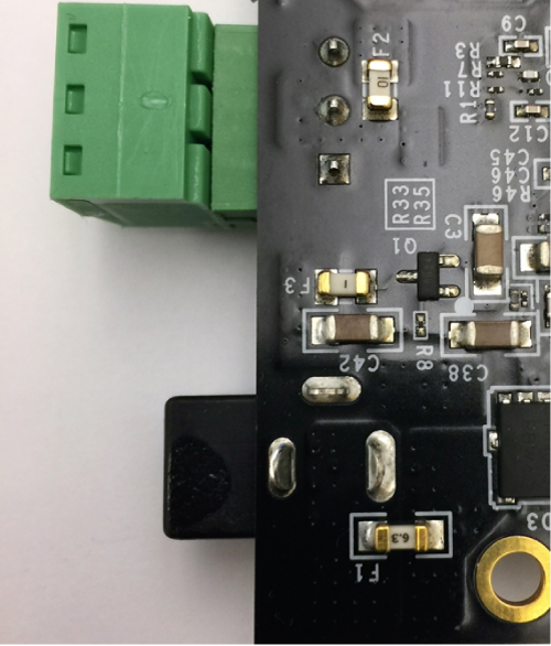
Figure 6. Fuses for overcurrent protection.
Operating Temperature Range
Analog Device’s Industrial ICs are specified to operate from -40°C to 125°C. However, the Intel Edison is limited to an operating temperature range of 0°C to 40°C. The user should take care not to exceed this temperature range for Pocket IO operation.
Detailed Description of Software
When building up a quick application, or when prototyping some feature, the quickest and easiest way to program Pocket IO, is through the Arduino application. Though not a full-code development, debugging environment, the Arduino sketch technique has a lot to offer, including:
- A familiar interface, instantly recognizable by many
- A full C/C++ compiler
- Access to many useful features built into the Linux OS resident in the Intel Edison processor
- Access to Pocket IO features through an included library
- Access to library updates as they become available
With so much capability packed into one small enclosure, the interface to manage all this is crucial. Each of Pocket IO's 10 resources has its own API. Figure 7 shows the software architecture for Pocket IO using Arduino IDE to compile code to run on the onboard Intel Edison CPU.
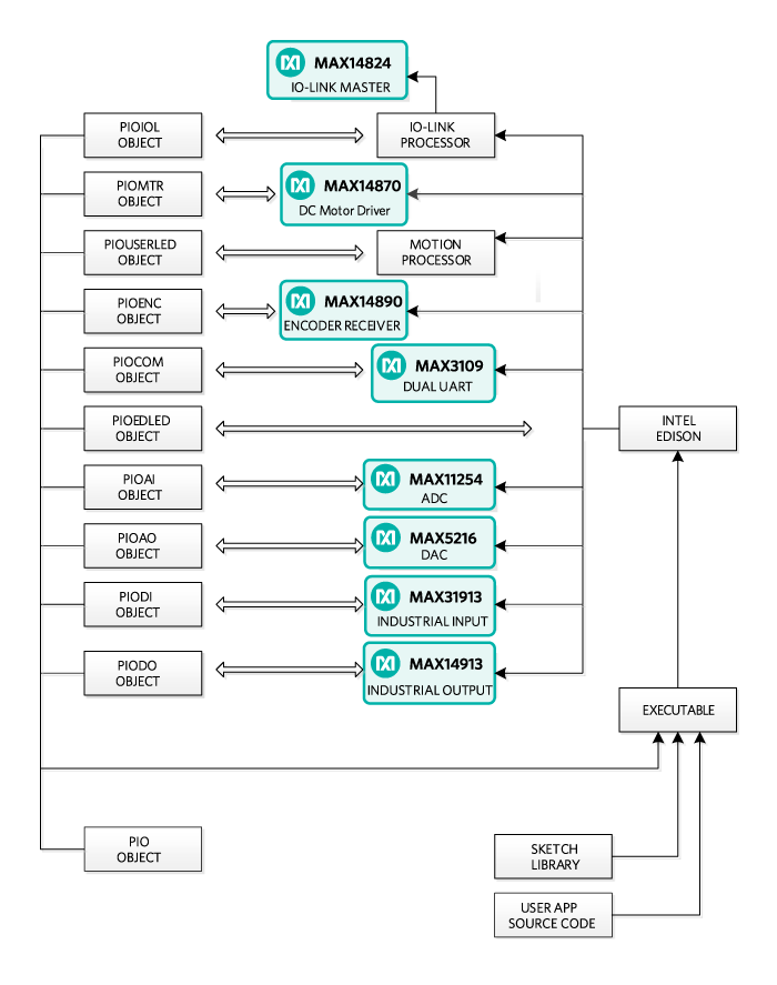
Figure 7. Pocket IO software architecture.
The following sections are details about API and some techniques, many Linux-specific, that enhance the capability of your applications.
Detailed Pocket IO API
These sections, organized alphabetically by Pocket IO feature, details the API available to control Pocket IO through sketch.
Note: For information about how to access software revision codes from Pocket IO, consult Boardinfo.ino in the Pio section of the Examples in sketch.
Analog Input
Pocket IO features two analog voltage inputs and two analog current inputs, all easily accessible through sketch. The voltage channels read anything between -12V and +12V whereas the current channels read anything between -24mA and +24mA. Pocket IO features a MAX11254 24-bit ADC featuring built-in two-point calibration compensation, which the API accommodates.
The API selects from among four channels, as follows:
| Channel | API Mnemonic | Attach Board Symbol |
| First Voltage | AI0 | AI0+/AI0- |
| Second Voltage | AI1 | AI1+/AI1- |
| First Current | AI2 | AI2 AI2+/AI2- |
| Second Current | AI3 | AI3 AI3+/AI3- |
| Note: The analog input and output circuitry grounds are isolated from the ground of the rest of Pocket IO. The AGND labels on the attach board indicate this separate analog ground. If you accidentally return an analog signal, either from one of the analog inputs or from the analog output, to the more common GND, there can be unexpected results. | ||
Calibration
The following code snippet shows how to perform a two-point calibration. Commonly, the user locks in the calibration, so it does not need to be done again, and calibration rarely needs to be done. Calibration comes in handy when attaching further circuitry to the analog inputs, and accuracy is to be maintained ahead of this extra circuitry. Pocket IO comes factory-calibrated for best accuracy at the connection points of the attach board.
The code snippet uses port AI0 as an example, but the code is the same regardless of which port is being calibrated. Each channel keeps its own unique calibration parameters.
// Makes Pocket IO analog input API available

// #include

PioAi pioAi; // Instances an analog input interface object

pioAi.init(); // Always needed for analog input pioAi.initCal(AI0); //Commences calibration

/*

* Put code here to apply +12 volts at the point of calibration

* if channel AI0 or channel AI1, or to apply +24mA if channel

* AI2 or AI3.

*

* Do not proceed until the voltage or current is applied and * stable.

*/

pioAi.setFullCal(AI0); // +12V or +24mA measured

/*

* Put code here to apply 0 volts or -24mA at the point of

* calibration.

*

* Do not proceed until the voltage or current is applied and * stable.

*/

pioAi.setZeroCal(AI0); // 0V or -24mA measured

delay(1000); // needed for ADC to calc corrections

// This method call takes the required corrections for that

// channel and stores it in non-volatile memory

pioAi.storeCal(AI0);
Reading an Analog Sample
Samples can be read either as a float or as a raw binary code from the ADC. The following code snippet shows how it is done. Because the sample rate is determined by the ADC itself, the user must select from one of the MAX11254 sample times as shown in the following table. Longer sample times result in readings with lower noise. This affects multiple sample reads. For example, with AI_RATE_1_9_SPS, after a first read, the thread calling a read method a second time is blocked for about 526msec.
| MAX11254 Sample Rate (sps) | API Mnemonic |
| 1.9 | AI_RATE_1_9_SPS |
| 15.6 | AI_RATE_15_6_SPS |
| 31.2 | AI_RSTE_31_2_SPS |
| 62.5 | AI_RATE_62_5_SPS |
| 250 | AI_RATE_250_SPS |
| 500 | AI_RATE_500_SPS |
| 1000 | AI_RATE_1000_SPS |
// Makes Pocket IO analog input API available

//

#include // no init() method

PioAi pioAi; // instances an analog input interface object

pioAi.init(); // always needed for analog input

// Loads a previously stored calibration for that channel,

// usually done once at setup

//

pioAi.restoreCal(AI0);

while (XXX)

{

// Reads one sample as a raw binary code

//

uint32_t code = pioAi.readCode(AI0, AI_RATE_1_9_SPS);

// The returned code is in offset binary, where 0V is

// 2^23, 12V is 2^23+2^23 = 2^24, and -12V is // 2^23 – 2^23 = 0

//

// In the case of current, the calibration is done is

// firmware, so the returned code is not relevant

// float toVolts = (float) (code – 8388608) * 12.0 / 8388608;

// Or you can do it easier this way, for reading current,

// this is the best way.

// float volts = pioAi.readFloat(AI0, AI_RATE_1_9_SPS);

}
Analog Output
Pocket IO provides one analog output, capable of any output voltage between 0V and 12V. Since there is only one analog output channel, there is no need to select channels. The API consists of only one method call, and no init() is needed for analog out.
The call to the method is a raw 16-bit code to the DAC. To drive a specific voltage, it must first be converted to a 16-bit equivalent for the DAC, as shown in the code snippet below.
// Makes Pocket IO analog output API available

// #include PioAo pioAo;

// instances an analog output interface object

const float DAC_CONV = 5443.106; // codes per volt

float voltageOut = 1.250; // desired output voltage

uint16_t codeDAC = (uint16_t) (voltageOut * DAC_CONV);

// Returns the argument to the method, as a uint16_t, which

// is usually ignored

//

uint16_t intCodeDAC = pioAo.writeCode(codeDAC);

// Could also do it this way

// uint16_t intCodeDAC = pioAo.writeCode(voltageOut * DAC_CONV);
Communications (RS-485)
Pocket IO provides serial communication through two RS-485 ports. Each port is half-duplex, and is preset for 115.2KBAUD at 8N2 (eight data bits, no parity, two stop bits).
Select from among the 2 channels as follows:
| Channel | API Mnemonic | Attach Board Symbol |
| 0 | COM0 | COM0A/COM0B |
| 1 | COM1 | COM1A/COM1B |
The API permits independent reading and writing for each channel. For any given channel, writes supersede reads. No harm occurs if multiple RS-485 transceivers drive a bus at the same time though this means any received data would be corrupted. Use protocol to ensure only one transceiver drives the bus at a time.
// Makes Pocket IO COMMS API available

// #include PioCom

pioCom; // instances a COMMS interface object

pioCom.init(); // always needed for COMMS

uint8_t bytes = {‘H’, ‘e’, ‘l’, ‘l’, ‘o’, ‘,’,’ ‘, ‘W’, ‘o’, ‘r’, ‘l’, ‘d’, ‘!’, \0};

// First param must be either COM0 or COM1

// Second param is a pointer to an array of bytes

// Third param is the number of bytes to transfer

//

// Maximum of 128 bytes can be sent. If a previous write

// has not yet completed, then the number of bytes that


// can be written is 128 – (number of bytes left to send)

// // If you send more than 128 bytes, the transmitted data

// will be corrupted. // PioCom.write (COM0, bytes, sizeof(bytes));
Reading data from an RS-485 port is similar to writing, with the added complication that you do not necessarily know how many bytes have been received. The following code snippet shows how to read data.
// Makes Pocket IO COMMS API available

//

#include PioCom pioCom;

// instances a COMMS interface object pioCom.init();

// always needed for COMMS

// Needed once before first read

// pioCom.clearInterrupts(COM0); uint8_t receiveBuffer [100]; uint8_t receiveCount;

// First param must be either COM0 or COM1

// Second param is an array to receive data

// Third param is the size of the buffer

// Fourth param will get the number of bytes actually read

//

// The receive buffer will be filled with a number of bytes

// received since a previous read method call. If this is less

// than the size of the buffer, then the buffer is

// partially filled. Otherwise, the buffer is filled and

// a subsequent read can obtain further read data.

//

// Note that data will be corrupted if more than 128 bytes

// have been received since a previous read method call.

//

// If there is no data, the fourth param will be set to zero

//

pioCom.read(COM0, receiveBuffer,

sizeof(receiveBuffer), &receiveCount);

// Do you want to test if there is pending data to be

// received? This method call returns the number of // bytes waiting to be read

//

// Useful for conditional mutex

//

uint8_t howManyBytes = pioCom.readRxFifoLevel(COM0);
Digital Input
Pocket IO has eight individual IEC-compliant industrial digital inputs. These inputs connect to binary sensors, such as limit switches, proximity sensors, distance sensors, and user switches. These inputs can be read individually, or as a group, through sketch.
Eight LEDs on the display panel indicate the state of each of these digital inputs. The LEDs are extinguished if driven low or left open, and illuminate when the corresponding input is driven logic high. The following table connects the individual inputs to the values returned through the API
| Channel | Bit Mask | API Mnemonic | Attach Board Symbol |
| 1 | 0x01 | DI1 | DI1 |
| 2 | 0x02 | DI2 | DI2 |
| 3 | 0x04 | DI3 | DI3 |
| 4 | 0x08 | DI4 | DI4 |
| 5 | 0x10 | DI5 | DI5 |
| 6 | 0x20 | DI6 | DI6 |
| 7 | 0x40 | DI7 | DI7 |
| 8 | 0x80 | DI8 | DI8 |
Additionally, the user has access to the debounce feature of the MAX31913 industrial digital input device. This feature reduces chattering of particularly noisy digital inputs. This debounce is global, applying to all digital inputs simultaneously used by Pocket IO. The following code snippet shows how to access these inputs as well as how to manage debounce.
// Makes Pocket IO digital input API available

//

#include PioDi pioDi;

// Instances a DI interface object pioDi.init();

pioDi.init(); // always needed for DI

// Gets all 8 inputs at once, correspondence between;

// bits and inputs given in the table above

// uint8_t allDigitalInputs = pioDi.readInput();

// Overloaded method also reads individual digital input

// channels. Returns ‘0’ or ‘1’

//

// In this case, checks the state of channel 7 only

// uint8_t specificDigitalInput = pioDi.readInput(DI7);

// This is how to set the debounce. Set as follows:

// 0x00 – no debounce

/ 0x01 – 25usec of debounce

// 0x02 – 750usec of debounce

// 0x03 through 0xff – 3msec of debounce

// A possibly corrected value is returned, for example if you

// try to set 0x10, 0x03 will be returned

// uint8_t realDebounce = pioDi.writeDebounce(0x02);

// The currently operational debounce setting can be checked

// uint8_t whichDeboucne = pioDi.readDebounce();
Digital Output
Pocket IO supports eight industrial digital outputs, each capable of driving 24V at greater than 640mA. The API supports many of the features of the MAX14913 or MAX14912 digital output driver IC, including output modes and fault detection.
Each digital output channel can be in one of two modes. High-side mode, as its name implies, only drives a channel high (nominal 24V). Many existing actuators and indicators work best in high-side mode. To have faster output driver switching, each output channel can also be configured to push-pull mode. Since both a high and a low are actively driven, there is no longer a natural decay of the wiring slowing down the transitions from high to low. The following table shows how to specify these through the API.
| Mode | API Mnemonic |
| High-Side | HS_MODE |
| Push-Pull | PP_MODE |
Each individual digital output can be driven high or low. The Pocket IO front panel allows easy confirmation of the output state, illuminating a green LED for each output being driven high. A matching red LED indicates that a fault has occurred on that output. This most commonly happens when accidentally tying two digital outputs together when they drive conflicting logic levels.
| Channel | Bit Mask | API Mnemonic | Attach Board Symbol |
| 1 | 0x01 | DO1 | DO1 |
| 2 | 0x02 | DO2 | DO2 |
| 3 | 0x04 | DO3 | DO3 |
| 4 | 0x08 | DO4 | DO4 |
| 5 | 0x10 | DO5 | DO5 |
| 6 | 0x20 | DO6 | DO6 |
| 7 | 0x40 | DO7 | DO7 |
| 8 | 0x80 | DO8 | DO8 |
The following code snippets show how to command the digital outputs and manage the mode settings of Pocket IO.
// Makes Pocket IO digital output API available

// #include PioDo pioDo;

// instances a DO interface object

// no init() method

// Commonly, set the output mode once before

// driving outputs

//

// first param:

// - 0x00 means set all to high-side more

// - 0x01 – 0xff means set all to push-pull mode

// pioDo.setModeAll(PP_MODE);

// can also set the mode of individual outputs

/ here, half of the outputs are set to high-side

/ for (int i = DO5; i <= DO8; i++) { pioDo.setMode(i, HS_MODE); }

// The mode can be confirmed through this method call

;

;

{ // code here for push-pull

} else {

// code here for high-side

}
The Pocket IO display panel indicates fault conditions on digital outputs by illuminating a red LED. This fault condition can also be detected through the API. There is a lot more to faults than can be described here, so for more details about fault conditions, refer to the MAX14912/MAX14913 data sheet.
// Is there a fault condition on digital output channel 4?

//

// The second argument indicates whether to clear faults or

// not. True causes faults to be cleared.

//

if (pioDo.readFault(DO4, false))

{

// we have a fault on DO4

}

// grab all the fault conditions at once

// If (pioDo.readFaultAll(true) & 0x0f)

{

// we have a fault on one or more of

// DO1 through DO4

}
Edison LED
Some Pocket IO resources are not directly related to industrial inputs and outputs. One of these resources is the two LED at the left of the display panel, labelled “EDISON STATUS.” One red and one green LED are purely under the user’s control. The LEDs can be used to indicate progress, status, or activity.
The following code snippet shows how to access the LEDs.
PioEdLed pioEd;

;// Instances an Edison LED object pioEd.init();>

// Always needed for Edison LED while (true)

{ pioEd.writeLed(GREEN, 0x01); // illuminate

delay(500);

pioEd.writeLed(RED, 0x01);

delay(500); pioEd.writeLed(GREEN, 0x00);

// extinguish delay(500);

pioEd.writeLed(RED, 0x00);

}
Encoders
Pocket IO has the capability to manage up to three motion-control channels. For many motion-control applications, controlling a motor is enough. For more precise scenarios, feedback is obtained, often from incremental encoders. This section discusses the three incremental encoder interfaces built into Pocket IO.
Incremental encoders communicate position information through two (most common), three (somewhat common) or four (less common) signals. Two-signal encoders are called A and B. Each edge communicates some fraction of a revolution. For example, when using a 4,000 pulses-per-revolution encoder, if you count only the rising edges of the A signal, you can see 1,000 such edges per revolution of the encoder shaft. If you count all edges of both the A and B signals, you can see 4,000 such edges per revolution of the encoder shaft. The timing of the A and the B signals is such that the direction can also be unambiguously determined. The Pocket IO incremental encoder interface uses the A and the B signals to maintain a position count based on the rising edges of the A signal.
A third signal, if it exists, is labelled the Z signal. Sometimes called an index pulse, this optional signal indicates the zero-degree point of the encoder shaft. Pocket IO currently ignores the Z signal. If a fourth signal exists, it is usually labelled the Y signal, and is used to indicate a fault condition in the encoder. Pocket IO has no means to connect to a Y signal.
Incremental encoders have been around for many decades now. Because of this, these encoders are available in a variety of signaling formats, and the MAX14890E encoder used in pocket IO is designed to handle this multiplicity.
Each signal has a “+” connection point and a “-” connection point. For example, the first encoder A signal connects through signals A1+ and A1-. How these are connected to depends on whether the signal format is single-ended or differential. For example, to connect a TTL A encoder signal to Pocket IO encoder channel 1, tie the signal to A1+, and tie the return to A1-. For differential signaling, tie the encoder A+ signal to A1+ and the encode A- signal to A1-. Because of the large common mode tolerance range of the MAX14890E used in Pocket IO, differential encoders usually function well even with no grounds tied between the encoder and Pocket IO.
Several front-panel LED indicators speak to the encoder interface. The yellow LED in the ENCODER section indicates encoder activity whereas the corresponding red LED indicates that an encoder channel has experienced a fault situation. Additionally, the yellow LED in the HS TERM section illuminates when Pocket IO attaches the high-speed RS-422 termination to the corresponding encoder channel.
Each Pocket IO encoder channel has its own signal format selection, communicated to the API by consulting the following table.
| Standard | API Mnemonic |
| Single-ended | SEHTL |
| Differential HTL | DHTL |
| RS-422 | RS422 |
| TTL | TTL |
Select from among the 3 encoder channels as follows:
| Channel | API Mnemonic | Attach Board Symbols |
| 1 | ENC1 | A1+, A1-, B1+, B1-, Z1+, Z1- |
| 2 | ENC2 | A2+, A2-, B2+, B2-, Z2+, Z2- |
| 3 | ENC3 | A3+, A3-, B3+, B3-, Z3+, Z3- |
This code snippet shows how to set encoder signal formats, and how to obtain encoder information.
// Make Pocket IO encoder API available

// #include PioEnc pioEnc;

// Instances an encoder interface object pioEnc.init();

// Always needed for encoders

// This sets the encoder 3 signal mode to TTL

// pioEnc.setMode(ENC3, TTL);

// The encoder interface maintains a position for each

// encoder. The position count is incremented for each

// clockwise pulse obtained by the encoder, and is

// decremented for each counterclockwise pulse of the

// encoder. So, if you read a position, move 500 pulses

// clockwise, then 499 pulses counterclockwise, your new

// position will be one count higher than the previous // position.

//

// The position is maintained as a 32-bit int, so commonly

// no overflow/underflow maintenance is needed in code.

//

// This is how to obtain the current position of encoder 1

/ You can also reset the encoder to zero at any time.

// pioEnc.initCount(ENC1);
IO Link
Pocket IO supports a 4 channel IO-Link master. This allows for control of up to four separate IO-Link devices, These devices can be sensors, actuators, communication hubs, etc. This enables the Pocket IO to expand on its already impressive offering of IOs. For instance, if all four IO-Link channels were connected to a x16 DI expander, this would increase the DIs of the Pocket IO to 64 + 8 = 72 total digital inputs.
The Pocket IO has four yellow LEDs for each IO-Link channel, labeled 1-4. If the specific IO-Link channel is initiated for communication, then the yellow LED is dimly lit. Note, these LEDs can be lit even if the protocol stack hasn’t been initiated for that channel, the device may be configured to enable in certain conditions in binary mode, hence lighting the LED. This is usually a brighter yellow than the yellow from the IO-Link communication. There are also two other LEDs with the label PROTOCOL underneath. If the red LED goes high, then this means the stack has had a hard fault and needs to be power cycled. This should not happen, but if it does power cycling is the only remedy.
The IO Attach Board has four M12 cable receptacles for attaching cables between the Pocket IO master and devices. These receptacles are slightly raised off the board, which may look like an error in assembly, but this is normal. The cables are to be inserted and screwed for a secure connection. This can be tricky so be sure to have the connector fully inserted. Also, make sure to have the device connected on the other end of the cable, and to have recorded which devices are on which channels. This is important for correct operation of the IO-Link stack.
| Channel | API Mnemonic | Attach Borad Symbol |
| 1 | 1 | IO-Link 1 |
| 2 | 2 | IO-Link 2 |
| 3 | 3 | IO-Link 3 |
| 4 | 4 | IO-Link 4 |
Assuming the physical connections and power are set, one must also install the appropriate IODD files onto the Pocket IO. This needs to be done for each unique IO-Link device, and only needs to be done once, unless new devices are added, in which case the new respective IODD files would need to be installed too. You will need to get these device IODD files from the device manufacturer, they should be in XML format. Once the files are obtained, connect a USB cable from the PC to the micro-USB port closest to the green power terminal. It may take a while as the PC discovers and installs the appropriate drivers, but the Pocket IO should eventually appear as a removable storage drive. It is most likely to appear as EDISON. Once available, drag and drop all desired IODD files onto the EDISON drive. Remember how you named these files and if they were in any subfolders, the complete file path is needed for use.
The Pocket IO IO-Link library can be broken up into 2 major parts, the setup and the application. The setup is always required and follows the same pattern. Please see the example code snippet below for the setup.
//Setup for IO-Link

//Include header for access to IO-Link library

#include

//Create instance of IO-Link object

PioIoLink pioIoLink;//note the instance can be named as desired

pioIoLink.init();//Always required, internal setup

//Set each channel to the appropriate IO-Link device

//Each must correspond to the appropriate IODD file path installed previously

pioIoLink.setChannelWithIoddFilePath( 1, “/RD27-IODD1.1.xml”);

pioIoLink.startIoLink(1);//start channel 1
The other major part would be the application. This could be requesting process data from the IO-Link device or writing to the ISDUs of the device. This can be done once or multiple times, and can determine the action of other IOs. The extent of use depends on the specific application but the code snippets below show how to use the basics; how to use the information is left to the user.
Below is a code snippet for collecting process data. It is assumed that you would have already called the setup snippet shown previously.
//IO-Link Process Data Snippet

//Assumes setup code already called

//Get byte length of process data in for channel 1

int length= pioIoLink.getProcessDataInLen(1);

//Create buffer with enough space for entire process data in

uint8_t buffer[length];

//Get process data into buffer from channel 1

pioIoLink.getProcessData(1, buffer, length);

//To make a decision based on the buffer information, some prior knowledge of

//what this data means is needed. This can be obtained from the manufacturer.

//For example, assuming length is 10, then we might check byte index 4, if it //greater than 2, then do something

if(buffer[4]>2){

//do something

}

//Again, this depends on the device and application

//Once the application is ready to finish, it is recommended to stop IO-Link.

//This might help, as the code will start automatically at power up, if the

//IO-Link device has been removed, say during power down, then the stack will //crash once

it tries to access, requiring another power up cycle.

//Close attention is required, but it isn’t strictly required to call the stop

pioIoLink.stopIoLink(1);//stop channel 1, recommended but not required
The other application example would be reading and/or writing to the ISDUs of the IO-Link device. It is not required to do both, either or is ok. Below is a code snippet for this case, it is assumed that you would have already called the setup snippet shown previously.
//IO-Link ISDU Snippet

//Assumes setup code already called

//Get byte length for ISDU 69 for channel 1

uint8_t isduLength = pioIoLink.getIsduByteLen(1, 69);

//Create buffer with enough space for entire ISDU

uint8_t buffer[isduLength];

//ISDU WRITE

//Assuming some prior knowledge about the device, say ISDU 69 was at least 2

//bytes long we might write

buffer[0] = 10;

buffer[1] = 130;

//Now we could write this new buffer value to ISDU 69

//Args in order, channel 1, isdu 69, subindex 0, data buffer, length of buffer

pioIoLink.writeIsdu(1, 69, 0, buffer, isduLength);

//END ISDU WRITE

//ISDU READ

//This time we could read from ISDU 69

//Args in order, ch 1, isdu 69, subindex 0, data buffer, ref to store length

pioIoLink.readIsdu(1, 69, 0, buffer, &isduLength);

//Now buffer contains data read from ISDU 69, and isduLength contains the actual byte

length of the ISDU read.

//END ISDU READ

//Actions on the buffer at this point depend on device and application

//Once the application is ready to finish, it is recommended to stop IO-Link.

//This might help, as the code will start automatically at power up, if the

//IO-Link device has been removed, say during power down, then the stack will //crash once it tries to access, requiring another power up cycle.

//Close attention is required, but it isn’t strictly required to call the stop

pioIoLink.stopIoLink(1);//stop channel 1, recommended but not required
For more detailed and accurate examples, please view the examples provided with the library.
Motor Control
A nice feature of Pocket IO is the ability to control up to three brushed DC motors. A separate green-colored connector supplies the motors, permitting the use of motors from 4.5V to 32V. During startup and other high-speed changes, each motor is limited to about two amperes of drive current. Because the motor driver is a full-bridge MAX14870 device, there is no ground connection to the motor, only to its two terminals.
The Pocket IO indicator panel shows the motor driving state for each motor port. A green LED illuminates when driving a motor clockwise, and a yellow LED illuminates when driving a motor counterclockwise. The higher the speed, the brighter the LED.
To adjust motor speed, Pocket IO provides an 8-bit PWM control for each motor independently. Select from among the 3 motor channels referring to the following table:
| Channel | API Mnemonic | Attach Board Symbol |
| 1 | M1 | M1+/M1- |
| 2 | M2 | M2+/M2- |
| 3 | M3 | M3+/M3- |
The API maintains a concept of rotation direction. When driving clockwise, the “+” connection averages a higher voltage than the “-“ connection. When driving counterclockwise, the “+” connection averages a lower voltage than the “-“ connection. The following table shows how to describe this.
| Direction | API Mnemonic |
| Clockwise | CLOCKWISE |
| Counterclockwise | COUNTERCLOCKWISE |
'Stopping' a motor can mean two different things. In one case, it can mean actively braking the motor with significant resistance to motion. In the other case, it can mean coasting, where there is little resistance to motion.
In the case of a DC-brushed motor, the difference can be significant. If the motor is part of some internal mechanism where there is no expected movement, then braking is the correct approach. With braking, forcing movement of the motor can prematurely wear out the motor brushes. However, if there can be movement of the motor after stopping, coasting is probably the better approach. The disadvantage of coasting is that the motor does not stop suddenly, so it can excurse past where you want to stop.
In some situations, you would like to stop motion solidly, but still permit a user to move a mechanism by hand. A good compromise in this situation is to brake the motor for a short time, and then coast the motor.
The following table summarizes the possible states of motion for the motors.
| State of Motion | Enable | Direction | Speed |
| Running one direction | True | CLOKCWISE | Any |
| Running other direction | True | COUNTERCLOKCWISE | Any |
| Braking | True | Any | Zero |
| Coasting | Flase | Any | Any |
The following code snippet shows how to manage the motors through Pocket IO.
// Make Pocket IO motor API available

//

#include PioMtr pioMtr; // Instances a motor interface object

// No init() needed

// Motor 1 to half speed one direction>

//

// The second argument to the writeSpeed method

// is between 0 (no motion) and 255 (full motion)

// pioMtr.writeEnable(M1, true); pioMtr.writeDirection(M1, CLOCKWISE); pioMtr.writeSpeed(M1, 128);

// half speed // Motor is running, want to reverse direction

// and still run at half speed // pioMtr.writeDirection(M1, COUNTERCLOCKWISE);

// Compromise stopping technique

/// First brake and then coast a short

// brake delay (100);

// good value for most small motors pioMtr,writeEnable(M1, false);

// now coast // The various values can be read back

// if (pioMtr.readEnable(M1))

{ // do something if M1 is enabled

} uint8_t myDirection = pioMtr.readDirection(M1);

uint8_t mySpeed = pioMtr.readSpeed(M1);
User LED
Some Pocket IO resources are not directly related to industrial inputs and outputs. One of these resources is the eight-user LED toward the bottom of the display panel, labelled “USER.” You have two blue, red, yellow, and green LEDs, that can be used to indicate anything (under the user’s control).
The following table correlates USER LED with code.
| User LED | API Mnemonic |
| 1 | LED1 |
| 2 | LED2 |
| 3 | LED3 |
| 4 | LED4 |
| 5 | LED5 |
| 6 | LED6 |
| 7 | LED7 |
| 8 | LED8 |
The following code snippet shows how to control the user LED.

// Makes Pocket IO user LED API available

// #include PioUserLed pioUser;

// Instances a user LED interface object

// init() method not needed

// This is how to control the user LED

//

// Illuminated LED if second param != 0

//

pioUser.writeLed(LED5, 1);

delay(1000); pioUser.writeLed(LED5, 0);

// Can also query the current state of any LED

//

uint8_t stateLED5 = pioUser.readLed(LED5);
Generally Useful Techniques
This section is a collection of tips and techniques that could be useful when writing more realistic programs. Some of these rely on Edison running Linux, with concomitant support in the sketch tool.
Debug Serial Port
Arduino sketch is great to get something up and running fairly quickly, but it does not support sophisticated debugging techniques such as breakpoints and watches. One possible solution is printing to a debug terminal. It turns out that you can print to the secondary “AUX USB” port in your programs, the same port that gives you shell access. The trick is to use “Serial2.xxx()”.
Using this method, you need to open and close the port once. After that, you can use the same methods useful in other sketches, such as “println()”, “print()”, “read()” and “available()”. Refer to the code sample below.
// Run this is the setup routine

//

Serial2.begin (115200);

Serial2.end ();

delay (100);

Serial2.begin (115200);

// Print some stuff

//

Serial2.print (“Hello world!\n”);

//

Serial2.end();
Digital Input Trick
Many makers learn early that putting an LED across a power supply without a current limiting resistor is bad for the health of the LED. However, industrial digital inputs naturally current limit to a few milliamps, so if you are prototyping, and want to make sure your DI is getting something like 24V, use an LED in series with the DI input. The current limit is about right to make most LEDs glow nicely.
Standardized Initialization Routine
For a routine to put MAXREFDES150# into a known and innocuous state, use the following code snippet. Call initPocketIO().
// File: pio_startup.hpp

//

// Standardized way to put Pocket IO into a

// clean and known state

//

// One main routine, can be used for startup and

// also for closing, and some individual smaller

// helper routines useful if you have threads

// dedicated to specific Pocket IO resources.

//

//****************************************

//

// Pocket IO specific stuff

//

//****************************************

#include

#include

#include

#include

#include

#include

#include

#include

// TODO: IO-Link

#include

#include

// Instance relevant Pocket IO objects

//

Pio pio;

PioAi pioAi;

PioAo pioAo;

PioCom pioCom;

PioDi pioDi;

PioDo pioDo;

PioEdLed pioEdLed;

PioEnc pioEnc;

// TODO: IO-Link

PioMtr pioMtr;

PioUserLed pioUserLed;

// Pocket IO initialization routines, puts

// everything into a known state

//

// These are the individual helpers that

// can be used for thread termination

oid initPioDo ()

{

// HS mode + set low == open output

//

pioDo.setModeAll (HS_MODE);

pioDo.writeOutputAll (0b00000000);

}

void initPioEdLed ()

{

pioEdLed.writeLed (GREEN, LOW);

pioEdLed.writeLed (RED , LOW);

}

void initPioEnc ()

{

pioEnc.setMode (ENC1, TTL);

pioEnc.setMode (ENC2, TTL);

pioEnc.setMode (ENC3, TTL);

}

void initPioMtr ()

{

pioMtr.writeEnable (M1, false);

pioMtr.writeEnable (M2, false);

pioMtr.writeEnable (M3, false);

pioMtr.writeSpeed (M1, 0x00);

pioMtr.writeSpeed (M2, 0x00);

pioMtr.writeSpeed (M3, 0x00);

pioMtr.writeDirection (M1, COUNTERCLOCKWISE);

pioMtr.writeDirection (M2, COUNTERCLOCKWISE);

pioMtr.writeDirection (M3, COUNTERCLOCKWISE);

}

void initPioUserLed ()

{

for (uint8_t whichUsr = LED1; whichUsr <= LED8; whichUsr++)

{

pioUserLed.writeLed (whichUsr, LOW);

}

}

// This is the method to call on startup to

// put everything into a known state

//

void initPocketIO (void)

{

// For board info

//

// Nothing to do

pio.init();

// For analog input

//

pioAi.init ();

pioAi.restoreCal (AI0);

pioAi.restoreCal (AI1);

pioAi.restoreCal (AI2);

pioAi.restoreCal (AI3);

// For analog output

//

// Nothing to do

pioAo.init();

// For COM port

//

pioCom.init ();

// For DI port

//

pioDi.init ();

// For DO port

//

pioDo.init();

initPioDo ();

// For Edison LED

//

pioEdLed.init ();

initPioEdLed ();

// For Encoders

//

pioEnc.init ();

initPioEnc ();

pioEnc.initCount (ENC1);

pioEnc.initCount (ENC2);

pioEnc.initCount (ENC3);

// For IO-Link

//

// TODO: Fill in later

// For motor drivers

//

pioMtr.init();

initPioMtr ();

// For user LED

//

pioUserLed.init();

initPioUserLed ();

}
Converting a Voltage Accurately Without Using Floating Point
For those who wish to get every ounce of performance they can, floating point math is to be avoided wherever possible. The MAXREFDES150# standard routines provide a readFloat method for analog input, but this uses a floating point to provide a value in volts. For voltage readings, we take advantage of the calibration registers built into the MAX11254ATJ. For this reason, after calibration, +12V always corresponds to a full-scale value from the readCode method, or 0x7fffff. With this knowledge, and a bit of integer math, we can convert the value from the readCode method to an accurate integer, representing the value in millivolts. Here is the technique:
// Vars

//

uint32_t rawCode; // 24-bit offset binary

int mVCode; // converted to mVolt

bool codeNegative; // avoids overflow

const uint32_t codeOffset = 8388608; // 2^23

// raw straight off the ADC

//

rawCode = pioAi.readCode (AI0, AI_RATE_1_9_SPS);

// Converts to int representing mVolt

// with no roundoff error

//

// Full scale is 12000mV = 375 * 32

// 131072 represents half an LSBit, because I want

// to round and integer math truncates

//

// 18 – need to divide by 2^23 to scale to unity,

// but multiply by 12000 = 375 * 2^5

//

if (rawCode >= codeOffset)

rawCode -= codeOffset;

codeNegative = false;

} else {

rawCode = codeOffset – rawCode;

codeNegative = true;

}

// must be uint32_t to avoid overflow

//

rawCode = ((rawCode * 375) + 131072) 18;

mVCode = codeNegative ? -rawCode : rawCode;
Doing Several Things At Once
When writing code more realistic than the examples given, it is often necessary to have multiple things happening at once. One traditional way to accomplish this, is to have a polling loop, continuously scanning for trigger conditions, and calling dispatch methods when appropriate. Though fast and effective, his method splits related code in multiple places, encourages convoluted coding, and soon becomes challenging to debug and maintain.
Fortunately, Linux supports threading, a feature that can be accessed from the sketch programs. Specifically, the OS build in Edison supports posix threads. With threads, you can have multiple snippets of code seemingly running at the same time. As if multiple sketches were running at the same time, only better.
The following code example runs a walking pattern on the USER LED and blinks the encoder LED simultaneously using threads. You need to copy some code above into a file name “pio-startup.hpp”, placed in the same folder as “SimpleThreading.ino.” The encoder code works because changing to RS422 mode engages the high-speed termination, and also indicates a fault failing from too low a voltage difference on the signals from the nonexistent encoders.
/// File: SimpleThreading.ino

///

/// Example non-mutex use of threading

///

/// For MAXREFDES150# Startup

///

/#include "pio_startup.hpp"

/// For POSIX threads and mutex

///

/include pthread.h

/pthread_t thrvUserLed; // POSIX thread handles

/pthread_t thrvEncLed;

/// User LED thread proper, does a

/// Cylon eye thing

///

/void *procUserLed(void *dum)

/{

/ int turnItOn, turnItOff;

/ int looper;

looper = 0;

while (true)

{

turnItOn = (looper < 6) ? (looper + 2) : (11 - looper);

turnItOff = (looper < 6) ? (looper ) : (13 - looper);

pioUserLed.writeLed (LED1 + turnItOn , HIGH);

pioUserLed.writeLed (LED1 + turnItOff, LOW );

looper = (looper + 1) % 12;

delay (100);

}

}

// ENC thread helper routine

//

void setEncMode (uint8_t mode)

{

pioEnc.setMode (ENC1, mode);

pioEnc.setMode (ENC2, mode);

pioEnc.setMode (ENC3, mode);

}

// Flashy little thing for encoder LED

//

void *procEncLed (void *dum)

{

while (true)

{

setEncMode (RS422);

delay (50);

setEncMode (TTL);

delay (50);

setEncMode (RS422);

delay (50);

setEncMode (TTL);

delay (50);

setEncMode (RS422);

delay (50);

setEncMode (TTL);

delay (2000);

}

}

// **************************************

// **************************************

//

// Arduino Sketch Startup specific code

//

// **************************************

// **************************************

// Sketch setup routine

//

void setup() {

// Starting state

//

initPocketIO ();

pioUserLed.writeLed (LED1, HIGH);

pioUserLed.writeLed (LED2, HIGH);

for (uint8_t i = LED3; i <= LED8; i++)

{

pioUserLed.writeLed (i, LOW);

}

setEncMode (TTL);

// Start worker threads

//

pthread_create (&thrvUserLed, NULL, procUserLed, NULL);

pthread_create (&thrvEncLed , NULL, procEncLed , NULL);

}

// Sketch run routine

//

void loop()

{

// work is all in the threads

//

delay (500);

}
Part of the reason the above code is so simple is that it never terminates. If you want to exit cleanly, there is a bit more work to do. It is common for each thread to clean itself up before exiting. For those threads that run continuously, you often see a global termination flag with each continuously running thread inspecting this flag regularly.
The issue is that you have no way to control which thread terminates before or after which other thread. This is where those thread handles come in handy. The trick is to make threads joinable, and then, when terminating, have code in the setup() or loop() methods wait for all the other threads to complete. This second step is called thread joining. In this context, joining means waiting for another thread to complete.
This code snippet replaces the two-thread, creates calls in the code above, and makes them joinable:
pthread_attr_t attrJoin; // allocate one attribute struct

pthread_attr_init (&attrJoin);

pthread_attr_setdetachstate (&attrJoin, PTHREAD_CREATE_JOINABLE);

// note second argument

pthread_create (&thrvUserLed, &attrJoin, procUserLed, NULL);

pthread_create (&thrvEncLed , &attrJoin, procEncLed , NULL);

pthread_attr_destroy (&attrJoin);
If you have cleanup code in your threads before they terminate, you need to wait for them to complete. In this example, you would add the following code at the place where you are waiting to end:
pthread_join (&thrvUserLed, NULL);

pthread_join (&thrvEncLed , NULL);

pthread_exit (NULL); // or else you keep looping
Keeping Threads From Interfering With Each Other
For a progress indicator follow this recommendation. After creating a thread that either blinks an LED or not, depending on the state of a flag, you can have other parts of your code turn the indicator on or off, at most any time. It’s possible to create a thread that looks at a flag; if the flag is set, blink an LED, and when the flag is reset, stop the blinking.
A potential problem arises if this flag can be touched in more than one thread. You need to protect two threads from trying to run over each other touching the flag. This common situation is also covered by POSIX, with something known as a mutex (stands for mutual exclusion). For each flag that needs this kind of protection, create a mutex and protect the flag by locking the mutex before you touch the flag; after unlock the mutex. You must do this everywhere your flag is touched because a locked mutex suspends any thread that tries to lock that same mutex until it is unlocked. It is also a good idea to declare the flag volatile. Actually, you have been using mutex all along and did not know. The MAXREFDES150# calls for the writeLed() method, for example, which are wrapped in an internal mutex in case you are calling from multiple threads.
The following code snippets show how this is done:
// Allocate a mutex and associated flag

//

pthread_mutex_t blinky_m = PTHREAD_MUTEX_INITIALIZER; bool blinky_f = false;

// Do this wherever you need to touch that flag

//

pthread_mutex_lock (&bllinky_m);

blinky_f = true;

pthread_mutex_unlock (&blinky_m);

// Remember to clean up your mutexes when you

// are done with them

//

pthread_mutex_dedtroy (&blink_m);
Keeping Timing More Accurate
The delay() method is very handy. It temporarily puts code to sleep. With threading, it provides more opportunities for other threads to run. The delay method, however, guarantees only a minimum delay. Especially when running multiple threads, a loop based on the delay function can appear jittery or slow.
The problem is the delay begins at the point the delay call is made, so any extra time taken to wake up from the delay method accumulates. We can go some way to alleviate this by causing wakeup at absolute times. This way, any extra time taken to wake up from the delay makes the next wakeup shorter.
The technique makes use of an OS structure called timespec, and a sleep based on absolute time. You start by grabbing the OS time, then you add a fixed increment to that time, and use that with a call to a function that says: “wake me up when your system clock reaches this time.” This is how we would modify the procUserLed thread above to trigger on absolute time:
// Near the top of the source file

//

#include

// Further down

//

void *procUserLed(void *dum)

{

int turnItOn, turnItOff;

int looper;

struct timespec myDelay;

// Get time now

//

clock_gettime (CLOCK_MONOTONIC, &myDelay);

looper = 0;

while (true)

{

turnItOn = (looper < 6) ? (looper + 2) : (11 - looper);

turnItOff = (looper < 6) ? (looper ) : (13 - looper);

pioUserLed.writeLed (LED1 + turnItOn , HIGH);

pioUserLed.writeLed (LED1 + turnItOff, LOW );

looper = (looper + 1) % 12;

// Add (in this case) 95msec to the time

// captured at the top and watch for

// overflow from nsec to sec

//

myDelay.tv_nsec += 100000000L;

if (myDelay.tv_nsec >= 1000000000L)

{

myDelay.tv_nsec -= 1000000000L;

myDelay.tv_sec++;

}

// Wake up at the new target time

//

clock_nanosleep (CLOCK_MONOTONIC, TIMER_ABSTIME, &myDelay, &myDelay);

}

}
IO-Link IODD Loading
Typically, when you get an IODD file from the manufacturer it is located in subfolders. The folders usually also include PNG files of graphics and logos. For the Pocket IO, these PNG files aren’t necessary and the subfolder structure may be burdensome. You might have noticed from the API section that if you intend to use a device’s IODD, you need to specify its file path with the method, setChannelWithIoddFilePath. This is usually a good reason to reduce the number of subfolders and the length of the IODD file name. Doing so can prevent simple errors from typos, and improve readability of the code.
It is also part of the API for the method that it returns true or false depending on whether it was able to find the specified file. This can be an insurance against typos, the file being deleted, or the code being loaded onto a new Pocket IO, that doesn’t have the IODD files yet. The code snippet below shows some ways to utilize this.
//Loading IODD files

//Note, this snippet only contains the content being discussed

bool success = false;//global used for success of IODD setup

void setup(){

//Get whether it can successfully find the IODD file and assign to channel 1

success = pioIoLink.setChannelWithIoddFilePath(1, “/yourIoddFilePath.xml”);

//Now check if successful, if so, start, otherwise abort

if(success){

pioIoLink.startIoLink(1);//start IO-Link for channel 1

}

else{

pioIoLink.clearAll();//unable to find or assign IODD, so clear

}

}

void loop(){

//Furthermore, it is a good idea to guard your IO-Link application code too

if(success){

//Only if success do more IO-Link stuff

}

}
Trying to Prevent IO-Link Faults and Crashes
If a fault occurs, the red LED above the PROTOCOL label might go on, or the yellow status LED for each of the IO-Link channels might begin to periodically flicker. These should not normally occur, but it is possible to accidently cause this. We will look at how this might happen and provide some solutions to help prevent them.
Firstly, if you have started IO-Link communication with a device and then physically disconnect the device, this causes the IO-Link stack to crash. One should never disconnect a device unless the IO-Link communication is stopped.
Secondly, make sure you have the correct device assigned to the channel. It is common for people to mix up which devices are connected to which channels, especially when all four channels are used and they are all different devices. Thus, if you call set Channel With Iodd File Path with the wrong IODD for that channel, it will return a success, because it found the appropriate IODD file at the path provided, but it does not behave as expected. The mismatch of devices determines the type of failure; it is unknown, but it is incorrect. Hence, it might cause a fault with the IO-Link stack. Therefore, try to double check that you have the correct IODD files assigned to the correct channels.
| IO-Link Channel | IO-Link Device | IO-Link IODD file path |
| 1 | MAXREFDES23# Light Sensor | "/RD23-IODD1.0.1.xml" |
| 2 | MAXREFDES27# Optical Prox | "/RD27-IODD1.1.xml" |
//Code snippet with mix up of IODDs and devices

//With the setup as above, THIS WILL CAUSE A CRASH

#include

PioIoLink pioIoLink;

bool success = false;

void setup(){

pioIoLink.init();

success = pioIoLink.setChannelWithIoddFilePath(1, “RD23-IODD1.0.1.xml”);

if(success){

pioIoLink.startIoLink(1);

}

else{

pioIoLink.clearAll();

}

//Here we set the WRONG IODD file path to channel 2

//However, it will still return true as we found the IODD file

success = pioIoLink.setChannelWithIoddFilePath(2, “RD23-IODD1.0.1.xml”);

if(success){

pioIoLink.startIoLink(2);//will cause errors

}

else{

pioIoLink.clearAll();

}

}
Thirdly and probably least obvious, is the condition where you have an IO-Link program loaded and it talks to channel 1 repeatedly. Say you power down the Pocket IO, and then remove the IO-Link device from channel 1. It would seem to be ok; however, if you then power on the Pocket IO, the program starts up again automatically and setChannelWithIoddFilePath returns true, as it would be able to find the IODD file and assign it, but then the stack crashes once it tries to communicate with the device that is no longer connected.
There are some circumstances where this might be ok. Say you upload new code to the Pocket IO and then power cycle again; this is ok. However, it is common to load new code and try it out before power cycling, and it might be unclear why the IO-Link stack is unresponsive. The Pocket IO does not recover until power has been cycled.
There are a couple of ways to prevent this from happening. The most secure way, but not always practical, would be to call the method, stopIoLink(uint8_t channel), for every channel you started. You would call this method once you were done with the IO-Link communication or the program was terminating.
//Code snippet with solution of stopping IO-Link communication

//Note, this is not also possible or practical, continue reading for another

//solution

//…skipping the usual setup code

void loop(){

//…skipping the application code

//This could be one way to terminate IO-Link communication once finished

//This would require the terminal connection and terminal window on PC

//Thus, once desired, the user could type any key to stop IO-Link comm

if(success && Serial2.available()){

pioIoLink.stopIoLink(1);

pioIoLink.stopIoLink(2);

Serial2.println(“Stopped”);

Success = false;

}

}
There are many cases where the program runs indefinitely; hence it only terminates once power is disconnected. In these situations, if you are going to remove devices and change the configuration, it is recommended to upload an example that doesn’t use the IO-Link stack, like the "PioEdLedBlink" example. Once it starts to run and you toggle the switch to make sure the program is saved to nonvolatile memory, it should be ok to turn off power and disconnect IO-Link devices. Thus, now on power-up it does not try to communicate with an IO-Link device that isn’t there, but merely toggles the LEDs; hence preventing the IO-Link from crashing.
Quick Start
Required equipment
- MAXREFDES150# Case (Pocket IO) with MAXREFDES150ATACH#
- Two 40-pin cable assemblies
- 24V, 1A power supply
- USB cable
- Windows® PC with a USB Port
- Arduino IDE Software
The first step is to connect the Pocket IO and the connector board, and then to install and configure the Arduino-based software tools.
Power Supplies
A single 24V, 1A supply is used to power the Pocket IO and internal DC-DC, and LDO circuits are used to generate the various different voltage levels required by the analog and digital devices.
Note: The maximum load this adapter can supply is 1A, which limits how many of the digital outputs are switching loads simultaneously since each of the eight outputs can handle loads of up to 640mA each. The user can use a different 24V supply with 5A (max) capacity. The 24V, 1A supply connects to the block barrel connector, shown on the left in Figure 2.
Connections
The main functional blocks are on the two PCBs within the Pocket IO case while the connectors are on a separate board, called MAXREFDES150ATACH# shown in Figure 3, which connects to Pocket IO using two 40-pin cable assemblies as shown in Figures 8, 9 and 10.
For testing MAXREFDES150# connect the Pocket IO boards in the plastic case to the MAXREFDES150ATACH# board using the two cable assemblies. Note each cable is the same, but one connector has a plastic 'key' to mate correctly to the male connectors on the MAXREFDES150ATACH# board. Start by connecting to the MAXREFDES150ATACH# board making sure the red line on the cable matches the Pin 1 triangle on J1 and J9 for the MAXREFDES150ATACH# board (Figure 8).
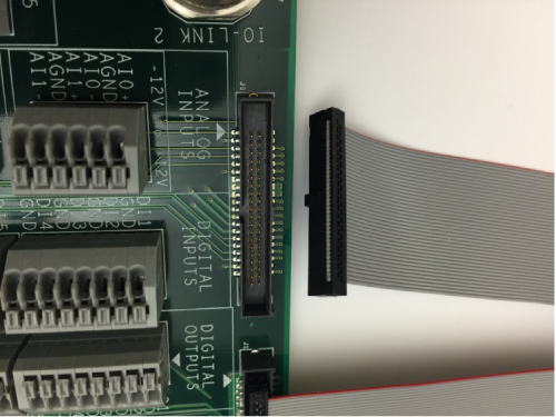
Figure 8. Connecting Cable Assembly to MAXREFDES150ATACH#.
Then connect the two cables to the male connectors at the rear of the Pocket IO plastic case; note how the red line on the cable is on the left hand side (Figure 7).
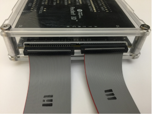
Figure 9. Cable Assembly to Pocket IO.
Make sure you do not cross the two cables (Figure 10).
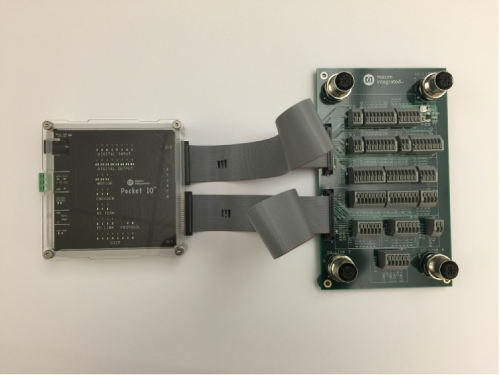
Figure 10. Pocket IO Connected to MAXREFDES150ATACH#.
Finally, take the 24V wall adapter and select the correct fixture for the local power outlet; the kit is supplied with adapters for England, Europe, USA and Australia standards (Figure 11).
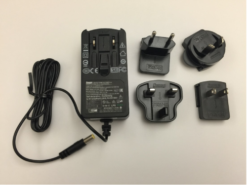
Figure 11. Pocket IO power supply and adapters.
Connect the 24V supply to the barrel connector on the plastic case (Figure 12).
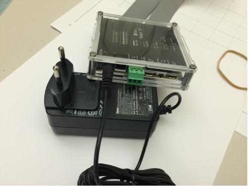
Figure 12. Pocket IO with Power Supply Connected.
Pocket IO is now ready to be powered on and tested. Testing requires a PC loaded with Arduino software for Pocket IO.
Procedure
Analog Devices Pocket IO Arduino Installation Instructions
- Download and install the latest Arduino IDE.
a. Go to https://www.arduino.cc/en/Main/Software.
b. Select the appropriate OS link (Windows, MAC®, Linux®). For this Quick Start we assume the OS is Windows PC.
c. Follow the prompts to download and save the file.
- Install the latest Arduino IDE.
a. Once the download has completed double click 'Arduino-x.x.xx-windows.exe.'
b. Windows then prompts you to run this file, select 'Run.'
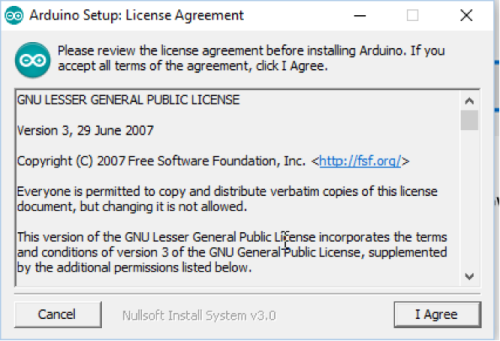
c. The Arduino setup displays the license agreement, select 'I Agree.'
d. It prompts you to select components to install, select 'Next.'
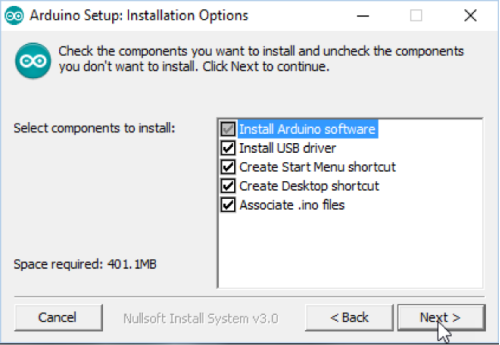
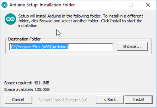
e. Next it shows the destination folder to install, select 'Install.'
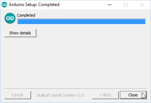
f. When Arduino setup is completed select 'Close.'
- Install Analog Device's Pocket IO Board.
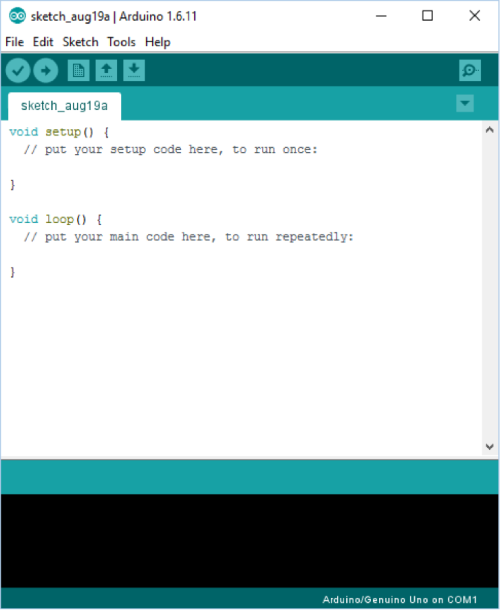
a. Locate the 'Arduino' shortcut on your desktop and double click the icon to open the Arduino IDE.
b. A window opens as shown below, select File > Preferences.
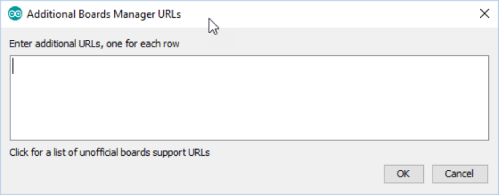
c. In the 'Preferences' window there is a section 'Additional Boards Manager URLs.' Select this box.

d. In the box that opens, copy and paste the URL below into this window and select 'OK', then 'OK' again. https://raw.githubusercontent.com/maximTicer/pocketio/master/package_maxim_index.json
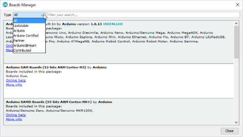
e. Select Tools > Board > Board Manager.
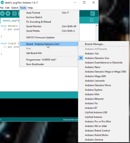
f. Open the 'Boards Manager' window and from the drop down Type menu select 'Certified.'
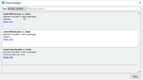
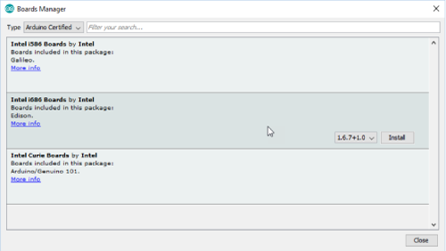
g. Select 'Intel i686 Boards by Intel' for Edison and click 'Install' to install rev 1.6.7+1.0 or later.
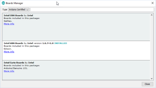
h. Once installation is completed, select 'Close.'
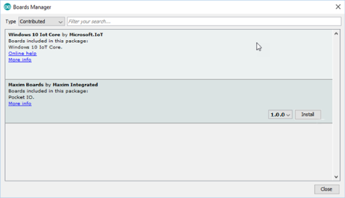
i. Open the 'Boards Manager' window and from the drop down Type menu select 'Contributed.'
j. Select 'Maxim Boards by Maxim Integrated' for Pocket IO, select the latest revision and click and click 'Install.'
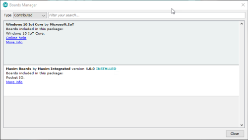
k. Once installation is completed, select 'Close.'
Note: If the user is updating from a previous release to a newer release of the Pocket IO Board Manager, it is necessary to follow all of these steps:
1. Do NOT use the"Update" button.
2. Click "Remove" button to uninstall the existing Pocket IO libraries.
3. Fully close, then re-open all the Arduino IDE windows.
4. Select the version from the drop down menu and click to "install" the updated version of Pocket IO libraries.
- Using the Pocket IO with Arduino IDE.
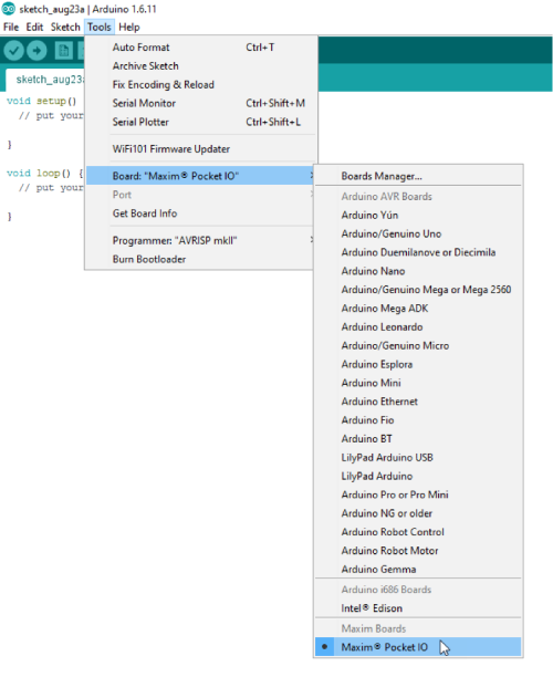
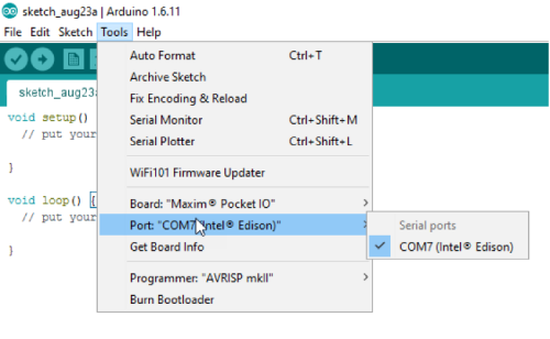
a. To select Pocket IO as the target board, select Tools > Board > Analog Devices Pocket IO.
b. Make sure Pocket IO is powered with 24V, and connect the USB cable to the micro-USB connector labeled 'Edison Status' (the one nearest to the green connector).
c. Select Tools > Port > COMXXX (where xxx is whichever COM port was selected when you plugged it in).
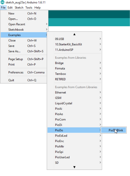
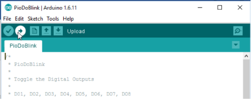
d. Next select File > Examples > PioDo > PioDoBlink.
e. A new window should appear with the example sketch selected. Press the circular button with the check mark in the top left corner to 'Verify' or compile the sketch.
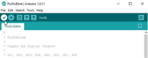
f. The window indicates it is compiling with a progress bar, and when finished, displays 'Done Compiling.'
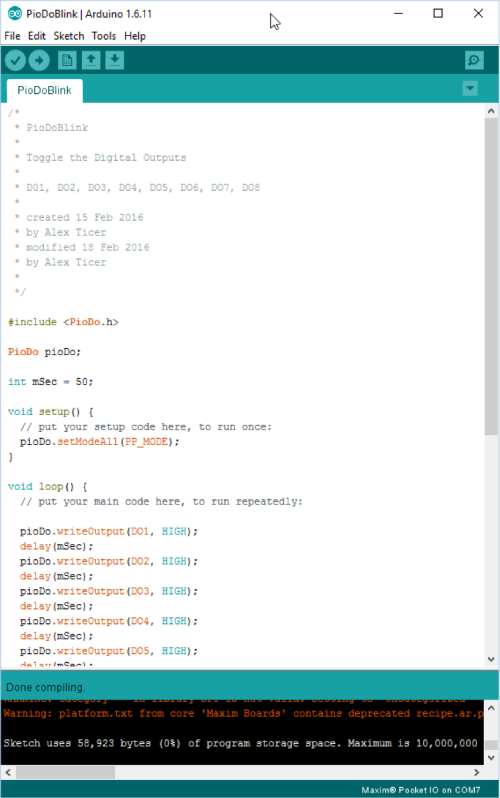
g. Now select the circular button with the right arrow, 'Upload' transfers the data to the Edison and starts to run the compiled program.
h. After a few seconds the message 'Done Uploading' is displayed and you can see the LEDs on the board flashing driven by the digital outputs.
i. A number of standard functions are included as examples to showcase the functionality of Pocket IO, or the user can develop their own sketches.
j. Analog Devices has loaded a Pocket IO image to the FLASH memory on the Edison module to replace the standard Edison image. Whenever the Pocket IO reboots, such as after power cycling, the last Arduino sketch is loaded by default. This is not the case for the standard Edison image. Pocket IO comes preconfigured with a sketch to blink the user LEDs.
Examples Showing Pocket IO in Typical Industrial Control Applications
Use Case – Digital Inputs and Digital Outputs
Here we discuss a possible subset of a real industrial control application. This setup consists of a light tower, with green, orange and red, representing normal, warning, and alarm statuses, respectively. The light tower is set by the digital outputs from the Pocket IO. There are also 2 inputs; one is an optical proximity sensor. This proximity sensor warns the user (orange light) if some equipment has come out of alignment and perhaps needs to be serviced. The sensor has been set to trigger at the appropriate distance away. The second input is a physical limit switch; if this is contacted it means a piece of equipment is about to collide and cause critical damage to the factory and hence an alarm (red light) should be set and the equipment halted. These go to the digital inputs of the Pocket IO. If neither input is tripped, then it is assumed that the factory is in a normal operating state (green light). Below is a table with the IOs for the application.
| IO | Device | Function |
| DI1 | Optical proximity sensor | Detect alignment issue, warning |
| DI2 | Physical limit switch | Detect imminent collision, alarm |
| DO1 | Light tower, green light | Normal status |
| DO2 | Light tower, orange light | Warning status |
| DO3 | Light tower, red light | Alarm status |
Below is a code snippet of what this might look like.
//Digital Input and Digital Output Industrial Control Application Example

#include

#include

PioDi pioDi;

PioDo pioDo;

//Previous state global

int prev = -1;//set to invalid value to ensure processing first time

void setup(){

//Init for digital inputs

pioDi.init();

//Init for digital outputs

pioDo.init();

pioDo.setModeAll(PP_MODE);

}

void loop(){

int cur = pioDi.readInput();//get current input reading from sensors

if(cur != prev){//state of system changed, take action

if(cur >= 2){//physical limit switch tripped

pioDo.writeOutput(0x04);//set red light for alarm status

}

else if(cur >= 1){//optical prox sensor tripped

pioDo.writeOutput(0x02);//set orange light for warning status

}

else{

pioDo.writeOutput(0x01);//set green for normal status

}

prev = cur;//always update previous status to current

}

}
Arduino is a registered trademark of Arduino, LLC.
ARM is a registered trademark and registered service mark and Cortex is a registered trademark of ARM Limited.
Beyond-the-Rails is a trademark of Analog Devices Integrated Products, Inc..
IEC is a registered service mark of the International Engineering Consortium, Inc.
Intel is a registered trademark and registered service mark of Intel Corporation.
IO-Link is a registered trademark of Profibus User Organization (PNO).
Linux is a registered trademark of Linus Torvalds.
Mac OS is a registered trademark of Apple Inc.
Pocket IO is a trademark of Analog Devices Integrated Products, Inc.
Wi-Fi is a registered certification mark of Wi-Fi Alliance Corporation.
Windows is a registered trademark and registered service mark of Microsoft Corporation.
Documentation & Resources
-
MAXREFDES150 Design Files2021/04/30ZIP55 M
-
Powering the Pocket IO PLC Development Platform2016/12/05PDF2M
-
フラッシュADCを理解する2001/10/02
Support & Training
Search our knowledge base for answers to your technical questions. Our dedicated team of Applications Engineers are also available to answer your technical questions.