


Overview
設計リソース
評価用ボード
型番に"Z"が付いているものは、RoHS対応製品です。 本回路の評価には以下の評価用ボードが必要です。
- MAXREFDES36# ($147.22) IO-Link® 16 Channel Digital Input Hub
デバイス・ドライバ
コンポーネントのデジタル・インターフェースとを介して通信するために使用されるCコードやFPGAコードなどのソフトウェアです。
説明
Introduction
Programmable logic controllers (PLCs) and distributed control systems (DCSs) use more digital inputs than any other input signal type combined. Running wires in parallel back to the PLC for industrial digital inputs is not only expensive but also creates a wiring rat’s nest that is difficult to maintain. Field buses improved the situation considerably by moving the I/O interface from the PLC to a remote I/O hub mounted close to the field sensors. However, the lack of a single, universally accepted field bus has also created confusion, training challenges, high costs, and compatibility issues among equipment.1
IO-Link is the first open, field bus agnostic, low-cost, point-to-point serial communication protocol used for communicating with sensors and actuators that has been adopted as an international standard (IEC 61131-9).2 IO-Link finally standardizes interoperability of industrial equipment from all over the world. IO-Link can function directly from the PLC or can be integrated into all standard field buses, quickly making it the defacto standard for universally communicating with smart devices like the MAXREFDES36#.
The MAXREFDES36# is an IO-Link 16-channel digital input hub that fits on a small 53.75mm x 72mm printed circuit board (PCB). Maxim Integrated and Technologie Management Gruppe Technologie und Engineering (TMG TE) collaborated in designing the MAXREFDES36# as an IO-Link version 1.1/1.0 compliant digital input hub reference design. The MAXREFDES36# design consists of an industry standard Maxim Integrated IO-Link device transceiver (MAX14821), an efficient high-voltage step-down converter (MAX17552), a Renesas® ultra-low-power 16-bit microcontroller (RL78) utilizing TMG TE’s IO-Link device stack and two Maxim Integrated digital input serializers (MAX31913).
機能と利点
Applications
- Digital input modules for PLCs
- Assembly lines
- Conveyor systems
- Robotics
- Process control and automation
- Industrial automation
- PLC and DCS systems
Competitive Advantages
- Small size
- Low power
- Low cost
Features
- DIN rail form factor
- IEC 61131-9
- IO-Link version 1.1 and 1.0 compliant
- On-chip 8:1 serialization
- Fault monitoring
- Field powered LED drivers
Details Section
The MAXREFDES36# IO-Link 16-channel digital input hub is made up of four main blocks: IO-Link transceiver, step-down converter, digital input serializers, and microcontroller as shown in Figure 1.
The MAX14821 IO-Link device transceiver is IO-Link version 1.1/1.0 physical layer compliant with configurable outputs (push-pull, pnp or npn), reverse-polarity/short-circuit protection, extensive fault monitoring all in a tiny 2.5mm x 2.5mm WLP package.
The MAX17552 high-voltage synchronous step-down converter efficiently converts 24V to 5V with an ultra-small footprint.
The MAX31913 is an octal digital input serializer with LED drivers for input port indication. Other features include configurable input current limiting, fault monitoring, and an internal 5V regulator. There are two cascaded MAX31913 devices on the board allowing 16 digital inputs.
An ultra-low-power RL78/G1A microcontroller with current consumption down to 66µA/MHz provides system control. It features 64kB on-chip programmable flash memory, 4kB on-chip data flash, and operates down to 1.8V, all in a tiny 3mm x 3mm LGA package.
Transient voltage suppressor (TVS) diodes are not all equal. The SDC36 TVS diodes have a clamping voltage less than 55V and meet both IEC 61000-4-2 (ESD) and IEC 61000-4-4 (EFT). There are many smaller TVS diodes on the market that cannot meet these specifications.
Push-in terminal blocks are used for all sixteen digital inputs, 24V, and ground. The 24V is provided by the IO-Link master and provides a minimum of 200mA per the IO-Link specification. The PCB fits in an enclosure with an industry standard DIN rail clip at the back as shown in Figure 2a.
The MAXREFDES36# was verified using TMG TE’s TMG IO-Link Device Tool V3, which comes with the purchase of the TMG-USB IO-Link master TS hardware. Contact TMG TE for more information. It was also verified using Balluff’s IO-Link Device Tool version 2.11.1, which comes with the purchase of the Balluff USB IO-Link master, part number BNI USB-901-000-A501 (see Figure 2b). Contact Balluff or one of their local distributors for ordering information. Download the IODD file (*.xml) located in the All Download Files section at the end of this document and go to the Quick Start section below for step-by-step instructions on how to use the software. Figure 3 shows a screen shot of the Balluff IO-Link Device Tool.
The MAXREFDES36# ships pre-programmed as a working IO-Link digital input hub ready to connect to an IO-Link master. The firmware targets a Renesas RL78 microcontroller and follows the simple flow chart shown in Figure 4. The firmware is written in C using the IAR embedded workbench from IAR Systems and utilizes TMG TE’s IO-Link device stack.
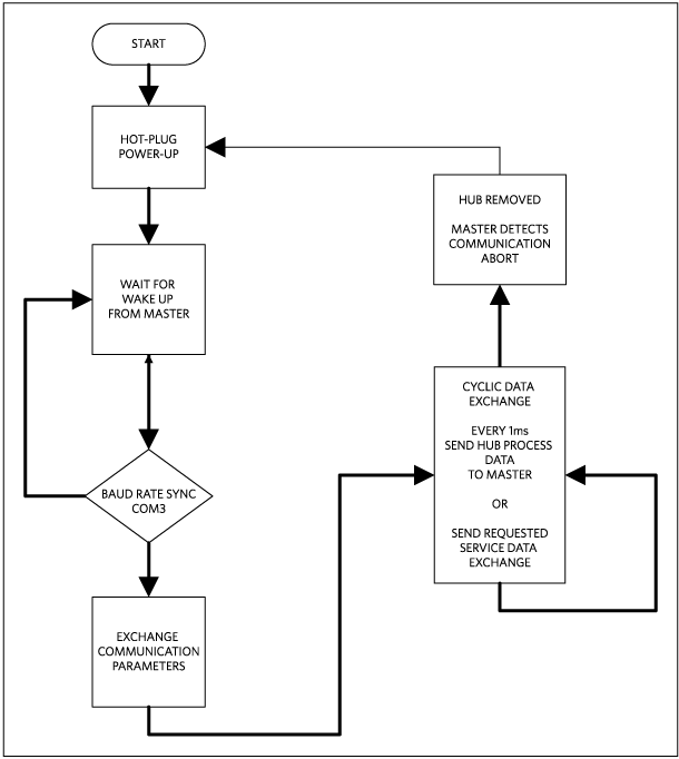
Figure 4. The MAXREFDES36# firmware flow chart.
After hot plug-in, the MAXREFDES36# waits for a wake-up signal from the IO-Link master. After receiving the wake-up signal, the MAXREFDES36# synchronizes to the IO-Link master’s 230.4kbps baud rate (COM3). Communication parameters are exchanged. The MAXREFDES36# then starts a cyclic data exchange every 1ms by sending the sensor process data to the IO-Link master. If the sensor is removed, the IO-Link master will detect a missing sensor.
There are two different use cases that you should consider before purchasing MAXREFDES36#. Use case 1 is simply using the MAXREFDES36#, which is pre-programmed to connect with a user-supplied IO-Link master and IO-Link cable as shown in Figure 5. Use case 2 is where the entire firmware development system is needed as shown in Figure 6.
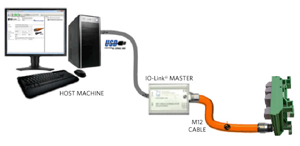
Figure 5. Use case 1 is the MAXREFDES36# quick start system.
| Use Case 1 (MAXREFDES36# Quick Start System) Company |
Description | Orderable Part Number |
| Maxim Integrated | IO-Link Digital Input Hub (ships programmed) | MAXREFDES36# |
| Balluff | USB IO-Link Master | BNI USB-901-000-A501 |
| Balluff | IO-Link Cable (4-wire/2m) | BCC05MC |
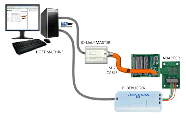
Figure 6. Use case 2 is the MAXREFDES36# firmware development system.
| Use Case 2 (RL78 IO-Link firmware development system—Renesas Starter Kit for RL78/G1A) Company |
Description | Orderable Part Number |
| Renesas Electronics | Renesas Starter Kit for RL78/G1A Includes: IAR Embedded Workbench for Renesas RL78 Santa Cruz (MAXREFDES23#) Programming Adaptor (MAXREFDES23DB#) |
YRL78IOLINKMAX |
| Maxim Integrated | IO-Link 16 Channel Digital Input Hub (ships programmed, but is reprogrammable) |
MAXREFDES36# |
| Renesas Electronics | E1 Programmer/Debugger | R0E000010KCE00 |
| Balluff | USB IO-Link Master | BNI USB-901-000-A501 |
| Balluff | IO-Link Cable (4-wire/2m) | BCC05MC |
Source code is only provided with use case 2, which is the Renesas Starter Kit for RL78/G1A. Contact Renesas Electronics for more information.
Required Equipment:
Purchased from Maxim:
- MAXREFDES36# board
User supplied:
- Windows® PC with a USB port
- Balluff USB IO-Link master, part number BNI USB-901-000-A501
- Balluff IO-Link Device Tool (tested with version 2.11.1 and comes with IO-Link master)
- M12 4-pin or 3-pin IO-Link cable (BCC05MC)
Note: Verify with Balluff that your version of Windows is supported before purchasing their software.
Download, read, and carefully follow each step in the MAXREFDES36# Quick Start Guide.
Equipment Used:
- Windows 7 PC with USB port
- MAXREFDES36# board
- Programming adapter (MAXREFDES23DB#) board
- Balluff USB IO-Link master, part number BNI USB-901-000-A501
- Balluff IO-Link Device Tool (tested with version 2.11.1 and comes with IO-Link master)
- M12 4-pin or 3-pin IO-Link cable
- RD36_RL78_V01_00.ZIP (IODD file); where XX_XX = latest version from webpage
- Fluke™ 189 Multimeter
- Tektronix® TDS2024B—4-channel 200MHz/2Gsps oscilloscope
Figure 7 shows the typical total hub current for changing values of both hub-powered digital input codes as well as for the more common field-powered digital input codes. The point of this figure is to show that the MAXREFDES36# provides field-side LED drivers, requiring no power from the hub. Figure 8 shows an oscilloscope screen shot of the cyclic data exchange every 1ms from the MAXREFDES36# to the IO-Link master.
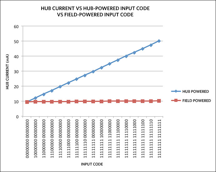
Figure 7. MAXREFDES36# HUB CURRENT vs. HUB-POWERED INPUT CODE vs. FIELD-POWERED INPUT CODE, IO-Link Power = 24V, at room temperature.
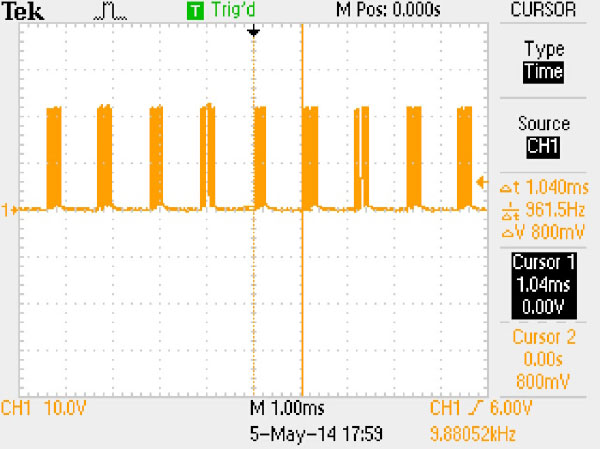
Figure 8. Cyclic data exchange every 1ms from the MAXREFDES36# to the IO-Link master.
- Fieldbus Inc's IEC61158 Technology Comparison study, Slide 58: "Fieldbus Technology Challenges".
- IO-Link System Description 2013 by IO-Link Company Community. Page 3, Preface.
Fluke is a registered trademark of Fluke Corp.
IO-Link is a registered trademark of ifm electronic GmbH.
Renesas is a registered trademark and registered service mark of Renesas Electronics Corp.
Tektronix is a registered trademark and registered service mark of Tektronix, Inc.
Windows is a registered trademark and registered service mark of Microsoft Corp.
Documentation & Resources
-
MAXREF36 Design Files2021/02/17ZIP1 M
Support & Training
Search our knowledge base for answers to your technical questions. Our dedicated team of Applications Engineers are also available to answer your technical questions.