LTM9002
NOT RECOMMENDED FOR NEW DESIGNS14-Bit, 125Msps Dual-Channel IF/Baseband Receiver Subsystem
- Part Models
- 4
- 1ku List Price
- Starting From $38.55
Part Details
- Integrated Dual 14-Bit, High-Speed ADC, Passive Filters and Fixed Gain Differential Amplifiers
- Up to 300MHz IF Range
- Lowpass and Bandpass Filter Versions
- Integrated Low Noise, Low Distortion Amplifiers
- Fixed Gain: 8dB, 14dB, 20dB or 26dB
- 50Ω, 200Ω or 400Ω Input Impedance
- Integrated Bypass Capacitance, No External Components Required
- 66dB SNR Up to 140MHz Input (LTM9002-AA)
- 76dB SFDR Up to 140MHz Input (LTM9002-AA)
- Auxiliary 12-Bit DACs for Gain Adjustment
- Clock Duty Cycle Stabilizer
- Single 3V to 3.3V Supply
- Low Power: 1.3W (665mW/ch.)
- Shutdown and Nap Modes
- 15mm × 11.25mm LGA Package
The LTM9002 is a 14-bit dual-channel IF receiver subsystem. Utilizing an integrated system in a package (SiP) technology, it includes a dual high-speed 14-bit A/D converter, matching network, anti-aliasing filter and two low noise, differential amplifiers. It is designed for digitizing wide dynamic range signals with an intermediate frequency (IF) up to 300MHz. The amplifiers allow either AC- or DCcoupled input drive. Lowpass or bandpass filter networks can be implemented with various bandwidths. Contact Analog Devices regarding customization.
The LTM9002 is perfect for demanding communications applications, with AC performance that includes 66dB SNR and 76dB spurious free dynamic range (SFDR). Auxiliary DACs allow gain balancing between channels.
A single 3V supply allows low power operation. A separate output supply allows the outputs to drive 0.5V to 3.3V logic. An optional multiplexer allows both channels to share a digital output bus. Two single-ended CLK inputs can be driven together or independently. An optional clock duty cycle stabilizer allows high performance at full speed for a wide range of clock duty cycles.
Applications
- Telecommunications
- Direct Conversion Receivers
- Main and Diversity Receivers
- Cellular Base Stations
Documentation
Data Sheet 1
Reliability Data 1
User Guide 1
Technical Articles 1
Product Selector Card 2
ADI has always placed the highest emphasis on delivering products that meet the maximum levels of quality and reliability. We achieve this by incorporating quality and reliability checks in every scope of product and process design, and in the manufacturing process as well. "Zero defects" for shipped products is always our goal. View our quality and reliability program and certifications for more information.
| Part Model | Pin/Package Drawing | Documentation | CAD Symbols, Footprints, and 3D Models |
|---|---|---|---|
| LTM9002CV-AA#PBF | 108-Lead LGA (15mm x 11.25mm x 2.32mm) | ||
| LTM9002CV-LA#PBF | 108-Lead LGA (15mm x 11.25mm x 2.32mm) | ||
| LTM9002IV-AA#PBF | 108-Lead LGA (15mm x 11.25mm x 2.32mm) | ||
| LTM9002IV-LA#PBF | 108-Lead LGA (15mm x 11.25mm x 2.32mm) |
| Part Models | Product Lifecycle | PCN |
|---|---|---|
|
Jul 21, 2021 - 21_0159 Ink Mark to Laser Mark Conversion for µModule |
||
| LTM9002CV-AA#PBF | LAST TIME BUY | |
| LTM9002CV-LA#PBF | LAST TIME BUY | |
| LTM9002IV-AA#PBF | LAST TIME BUY | |
| LTM9002IV-LA#PBF | LAST TIME BUY | |
This is the most up-to-date revision of the Data Sheet.
Software Resources
Evaluation Software 1
LinearLab Tools
A collection of Matlab and Python programs that provide direct access to Linear Technology’s data converter evaluation boards.
Hardware Ecosystem
| Parts | Product Life Cycle | Description |
|---|---|---|
| PLL Synthesizers 1 | ||
| LTC6946 | LAST TIME BUY | Ultralow Noise and Spurious 0.37GHz to 6.39GHz Integer-N Synthesizer with Integrated VCO |
Evaluation Kits
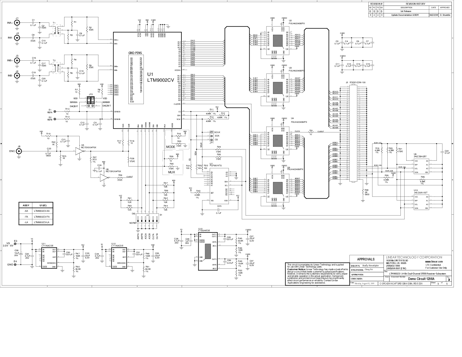
LTM9002-AA | 14-Bit, 125Msps, DC-170MHz LPF, 26dB Gain, 12-Bit SPI Trim DAC (Requires DC890)
Resources
Latest Discussions
No discussions on LTM9002 yet. Have something to say?
Start a Discussion on EngineerZone®