Design Note 420: USB Power Solution Includes Switching Power Manager, Battery Charger, Three Synchronous Buck Regulators and LDO
Introduction
Linear Technology offers a variety of parts to simplify the task of extracting power from a battery or a USB cable. These devices seamlessly manage the power flow between an AC adapter, USB cable and Li-Ion battery, all while maintaining USB power specification compliance. As battery capacities rise, battery chargers must keep pace by steadily improving efficiency to minimize thermal concerns and charge times. A USB-based battery charger must squeeze as much power from the USB as possible and do it efficiently to meet the stringent space and thermal constraints of today’s power-intensive applications.
The LTC3555 combines a USB switching power manager and battery charger with three synchronous buck regulators and an LDO to provide a complete power supply solution in one small (4mm × 5mm) package (Figure 1). The constant-current, constant-voltage Lithium-Ion/Polymer charger utilizes a Bat-Track feature to maximize the efficiency of the battery charger by generating an input voltage that automatically tracks the battery voltage (described below). An I2C serial interface affords the system designer complete control over the charger and the DC/DC bucks for ultimate adaptability to changing operating modes in a wide range of applications.

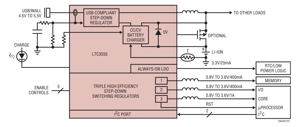
Figure 1. All-in-One USB Power Solution Includes Switching Power Manager, Battery Charger, Three Synchronous Buck Regulators and LDO.
Switching PowerPath Controller Maximizes Available Power to the System Load
The LTC3555 improves over earlier generations of USB battery chargers with the addition of several new features. It uses a proprietary switching power manager to extract power from a current-limited USB port with the highest possible efficiency, while maintaining average input current compliance. It minimizes power lost in the linear charger with its Bat-Track feature.
First generation USB applications implemented a current-limited battery charger directly between the USB port and the battery, where the battery voltage powers the system. This is referred to as a battery-fed system. In a battery-fed system, the available system power is IUSB • VBAT because VBAT is the only voltage available to the system load. When the battery is low, nearly half of the available power is lost to heat within the linear battery charger element.
Second generation USB chargers developed an intermediate voltage between the USB port and the battery. This intermediate bus voltage topology is referred to as a PowerPath™ system. In PowerPath ICs, a current limited switch is placed between the USB port and the intermediate voltage. The intermediate voltage, VOUT, powers the linear battery charger and the system load. By using the intermediate bus voltage topology, the battery is decoupled from the system load and charging may be carried out opportunistically. PowerPath systems have the added benefit of being “instant-on” because the intermediate voltage is available for system loads as soon as power is applied to the circuit, independent of the state of the battery. In a PowerPath system, more of the 2.5W available from the USB port is made available to the system load as long as the input current limit has not been exceeded. PowerPath systems offer improvements over battery-fed systems, but significant power may still be lost in the linear battery charger element if the battery voltage is low.
The LTC3555 is the first IC in the third generation of USB PowerPath chargers. These PowerPath devices produce an intermediate bus voltage from a USB-compliant step-down regulator that is regulated to a fixed amount over the battery voltage (a Bat-Track feature). The regulated intermediate voltage is just high enough to allow proper charging through the linear charger. By tracking the battery voltage in this manner, power lost in the linear battery charger is minimized, efficiency increases and power available to the load is maximized.
Figure 2 provides an efficiency comparison and power savings between chargers with switching vs linear PowerPath systems. The amount of power saved while charging large batteries can make the difference between a device that runs in thermal limit and one that runs cool.

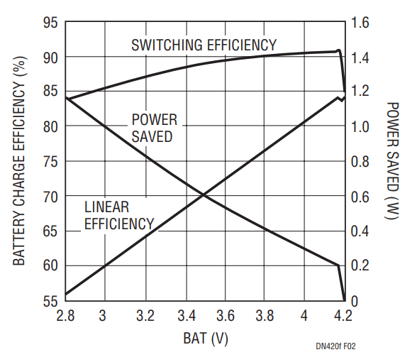
Figure 2. Switching PowerPath Battery Charger Efficiency and Power Savings Relative to a Linear Charger. (VBUS = 5V, 5X MODE, RCLPROG = 2.94k, RPROG = 1k, IBAT = 0.7A at VBAT = 2.8V).
Complete Power Solution in a Single IC
The LTC3555 also contains three user configurable step-down DC/DC converters capable of delivering 0.4A, 0.4A and 1A. Regulator 1 has a fixed reference voltage of 0.8V while regulators 2 and 3 may have their reference voltage changed via the I2C interface between 0.8V and 0.425V. All of the converters operate at a switching frequency of 2.25MHz, allowing the use of small passive components while maintaining efficiencies up to 92% for output voltages greater than 1.8V (see Figure 3). All three regulators may be programmed to operate in pulse-skipping mode, Burst Mode® operation or LDO mode via the I2C port or through I/O pins. In Burst Mode operation the output ripple amplitude is slightly increased and the switching frequency varies with the load current to improve efficiency at light loads. If noise is a concern, all of the regulators may be set to operate in LDO mode or pulse-skipping mode. The device also provides an always-on 3.3V output capable of delivering 25mA for system needs such as a real-time clock or pushbutton monitor.

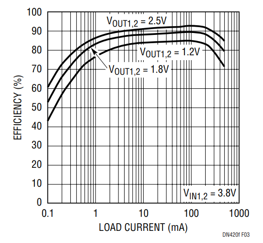
Figure 3. Efficiency of Switching Regulators 1 and 2 with Burst Mode Operation.
Conclusion
The LTC3555 is an advanced and complete power solution in a single chip. The third generation PowerPath management technology with its reduction in both heat generation and battery charge time is ideally suited for tomorrow’s high density, feature rich battery-powered products. By integrating three I2C-controlled, highly efficient step-down DC/DC converters, the LTC3555 allows the system designer complete flexibility to adapt to changing demands and operating modes.
Author